T
Variomat Touch — 09.09.2022-Rev. C
English —
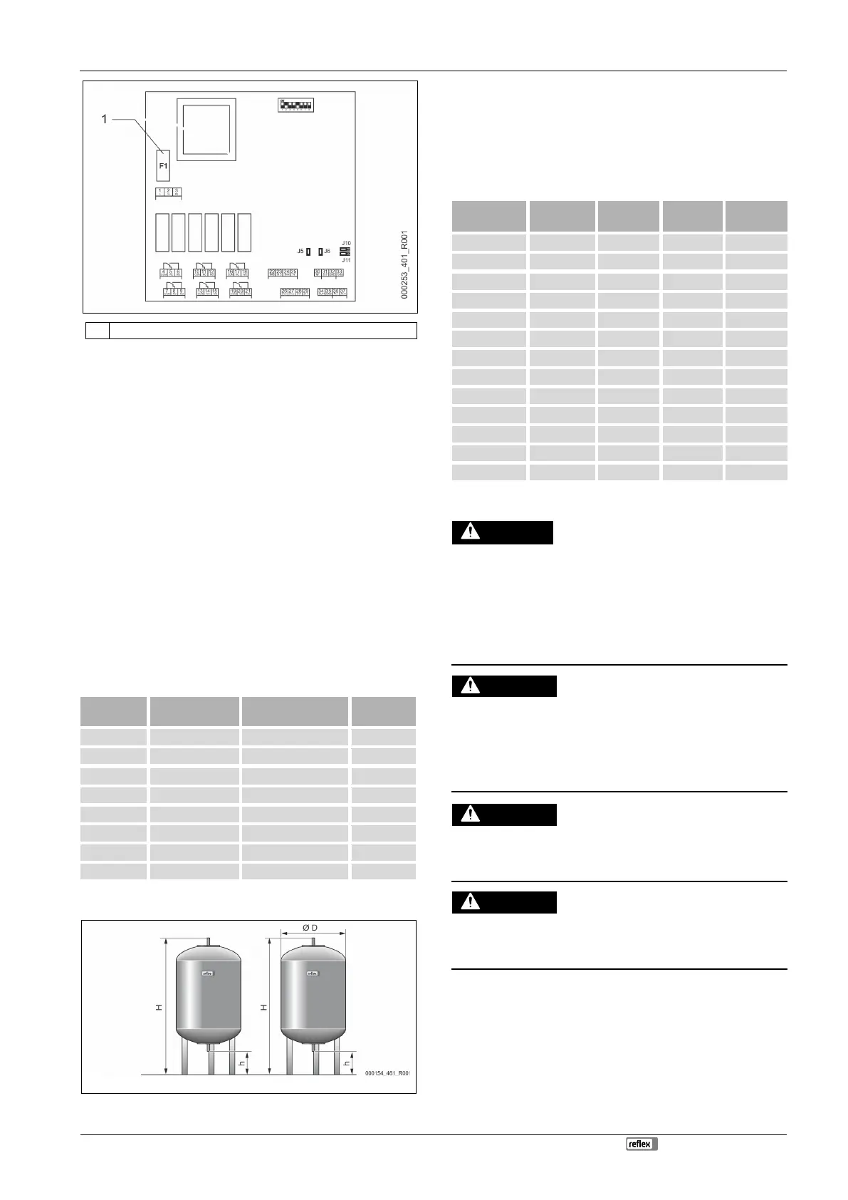
1 Microfuse F1 (250 V, 0, 16 A slow)
Proceed as follows:
1. Disconnect the I/O module from the power supply.
• Pull the power plug from the bus module.
2. Open the terminal space cover.
3. Remove the housing cover.
4. Replace the defective fuse.
5. Re-attach the housing cover.
6. Close the terminal space cover.
7. Reconnect the power supply for the module.
The fuse replacement is completed.
6 Technical data
6.1 Control unit
Note!
The following values apply for all control units:
– Permissible flow temperature:
–
Permissible operating temperature:
Permissible ambient temperature:
Degree of protection:
Number of RS-485 interfaces:
IO module:
Electrical voltage control unit:
70 °C
0 °C – 45 °C
IP 54
1
Optional
230 V; 2 A
Electrical connection
[Hz; A]
VS 2-1/35 1.1 50; 5 29
VS 2-1/60 1.1 50; 5 37
VS 2-1/75 1.1 50; 5 50
VS 2-1/95 1.1 50; 5 53
VS 2-2/35 1.2 50; 5 58
VS 2-2/60 2.2 50; 10 61
VS 2-2/75 2.2 50; 10 89
VS 2-2/95 2.2 50; 10 92
6.2 Tanks
Primary tank Secondary tank
Note!
Optional heat insulation is available for primary tanks,
4.6 "Optional
equipment and accessories",
Note!
The following values apply for all vessels:
Connection:
G1 "
200 634 37 1060 146
300 634 54 1360 146
400 740 65 1345 133
500 740 78 1560 133
600 740 94 1810 133
800 740 149 2275 133
1000/740 740 156 2685 133
1000/1000 1000 320 2130 350
1500 1200 465 2130 350
3000 1500 795 2590 380
4000 1500 1080 3160 380
5000 1500 1115 3695 380
7 Installation
Risk of serious injury or death due to electric shock.
If live parts are touched, there is risk of life-threatening injuries.
• Ensure that the supply cable to the device is disconnected and secured
against being switched back on.
• Ensure that the system is secured and cannot be reactivated by other
persons.
• Ensure that installation work for the electric connection of the device is
carried out by an electrician, and in compliance with electrical locally
applicable electrical engineering regulations.
Risk of injury due to pressurised liquid
If installation, removal or maintenance work is not carried out correctly, there
is a risk of burns and other injuries at the connection points, if pressurised
hot water or hot steam suddenly escapes.
• Ensure proper installation, removal or maintenance work.
• Ensure that the system is de-pressurised before performing installation,
removal or maintenance work at the connection points.
Risk of burns on hot surfaces
Hot surfaces in heating systems can cause burns to the skin.
• Wear protective gloves.
• Please place appropriate warning signs in the vicinity of the device.
Risk of injury due to falls or bumps
Bruising from falls or bumps on system components during installation.
• Wear personal protective equipment (helmet, protective clothing,
Note!
Confirm that installation and start
-up have been carried out correctly
using the installation, start
-up and maintenance certificate. This action
is a prerequisite for the making of warranty claims.
Have the Reflex Customer Service carry out commissioning and
 Loading...
