Variomat Touch — 09.09.2022-Rev. C
English —
22b FB2b --- ---
23 NC
Group message (potential free)
Max. 230 V, 2 A
On-site 24 COM
25 NO
27 M1
Flat plug for supply, pump 1
Factory-
provided
31 M2
Flat plug for supply, pump 2
Factory-
provided
35 +18 V (blue)
Analogue input, LIS level
measurement
at the primary vessel
Cable:
factory-
provided;
Sensor plug:
on-site
36 GND
37 AE (brown)
38 PE (shield)
39 +18 V (blue)
Analogue input, "PIS" pressure
measuring
at the primary vessel
On-site,
optional
40 GND
41 AE (brown)
42 PE (shield)
43 +24 V
Digital inputs
On-site,
optional
44 E1 E1: Contact water meter
Factory-
provided
45 E2 E2: Low water switch ---
PV 2 overflow valve (motor ball
valve), only in VS 2-2
Factory-
provided
52 +24 V (supply)
53
0 – 10 V
(correcting
variable)
54
0 – 10 V
(feedback)
55 GND
PV 1 overflow valve (motor ball
valve)
Factory-
provided
56 +24 V (supply)
57
0 – 10 V
(correcting
variable)
58
0 – 10 V
(feedback)
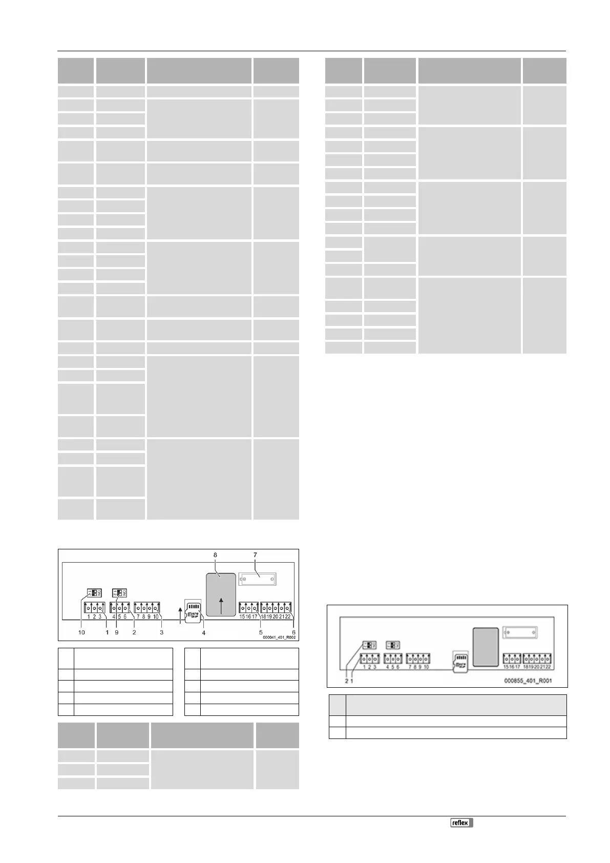
7.5.3 Terminal plan, operating unit
1 RS-485 interface 6
Analogue outputs for Pressure
and Level
2 RS-485 interface 7 Battery compartment
3 I/O interface 8 Anybus module slot
4 Micro-SD card 9 DIP switch 2
5 10 V supply 10 DIP switch 1
1 A
RS-485 interface
S1 networking
On-site 2 B
3 GND S1
4 A
RS-485 interface
S2 modules: Expansion or
communication module
On-site 5 B
6 GND S2
7 +5 V
I/O interface: Interface to the
main board
Factory
8 R × D
9 T × D
10 GND IO1
11 ---
--- ---
12 ---
13 ---
14 ---
15
10 V~
10 V supply Factory 16
18
Y2PE
(shielding)
Analogue outputs: Pressure and
Level
Standard 4 – 20 mA
On-site
19 Pressure
20 GNDA
21 Level
22 GNDA
7.5.4 RS-485 interface
Use the S1 and S2 RS-485 interfaces to retrieve all controller data and to enable
the communication with control centres or other devices.
• S1 interface
– A maximum 10 devices can be used in a master-slave linked circuit
via the this interface.
• S2 interface
– "PIS" pressure and "LIS" level.
– Operating modes of the "PU" pumps.
– Operating states of the motorised ball valve/solenoid valve.
– Values of the "FQIRA +" contact water meter.
– All messages.
– All entries in the fault memory.
The following bus modules form part of the optional accessories available for
interface communication.
Note!
If required, please contact the Reflex Customer Service for the protocol
of the RS
-
485 interface, details of the connections and information about
the accessories offered.
7.5.4.1 Connecting the RS-485 interface
Main board of the Control Touch controller.
1 Connection terminals for RS-485 connection
2 Dip switch 1
Proceed as follows:
1. Use a screened cable to connect the RS-485 interface to the main board.
• S 1
– Terminal 1 (A+)
– Terminal 2(B-)
– Terminal 3(GND)
 Loading...
