DRIVE AND CUTTING MECHANISM
7-3
Tape Marker
C532
C532 SM
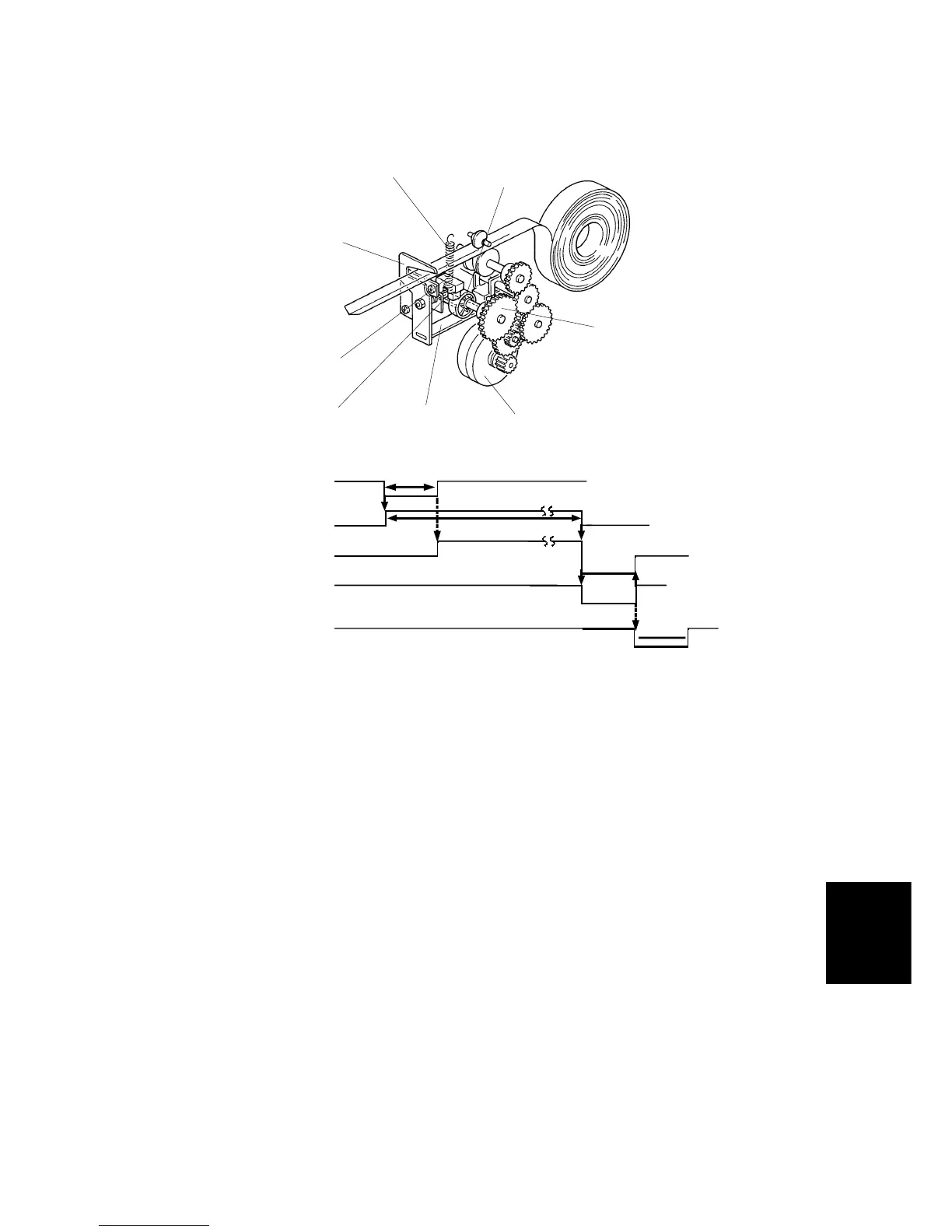
2.2 DRIVE AND CUTTING MECHANISM
The tape dispenser uses a stepping motor, which is driven at 460 pulses per
second, as a drive motor.
When the print counter of the main body becomes 0, the start signal from the main
body changes from high (+5 VDC) to low (0 VDC) to start the timer on the tape
dispenser board. When the start signal changes to high 10 milliseconds later, the
drive motor [A] starts to rotate counterclockwise to feed tape. However, since a
one-way bearing is mounted in the cam drive gear [B], the cutter cam [C] does not
rotate.
The drive motor starts rotating in the opposite direction 2,500 milliseconds after the
timer starts. At this time, the tape has been fed out 250 mm (9.8") from the tape
dispenser. The drive motor rotates the cam drive gear clockwise and the eccentric
shaped cutter cam presses down the cutter arm [D]. The cutter [E] then goes down
to cut the tape. The cutter spring [F] returns the cutter to its original position. After
the cutter home position sensor [G] detects the cutter actuator [H], the drive motor
stops and the tape dispenser board sends the task completion signal to the main
body.
C532D502.PCX
10 ms
2500 ms
Forward
Reverse
100 ms
Start Signal
Timer
Drive Motor
Task Completion
Signal
Home Position
Sensor
C532D503.WMF
[A]
[B]
[E]
[F]
[G]
[H]
[D]
[C]