INSTALLATION PROCEDURE
3-18
C231/C237/C238 SM
3.2.5 INTERFACE BOARD (OPTION)
Accessory Check
Check the quantity and condition of the accessories in the box against the following
list:
1. Interface Board ................................................................... 1
2. Interface Harness................................................................ 1
3. Screw M3 x 6 ...................................................................... 2
4. Lock Screws........................................................................ 2
5. Washer................................................................................ 2
Installation Procedure
1. Turn off the main switch and unplug the power cord.
2. Remove the upper rear cover.
3. Remove the MPU cover.
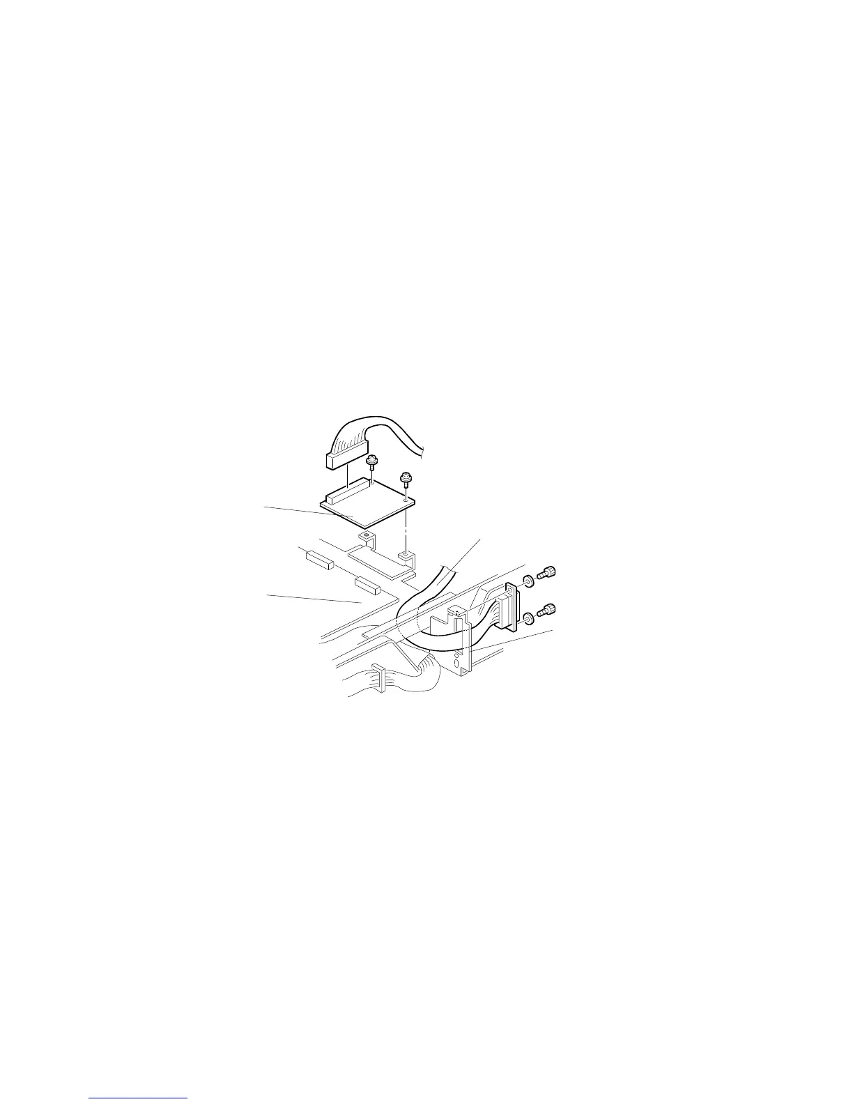
4. Connect CN102 of the interface board [A] to CN110 [B] of the MPU board and
secure it using two screws.
5. Connect the harness [C] to CN101 of the interface board, and secure it to the
connector bracket [D] using two lock screws and washers.
6. Remove the communications port cover plate from the upper rear cover.
7. Reinstall the MPU cover.
8. Reinstall the upper rear cover.
C532I533.PCX
[A]
[B]
[C]
[D]