INSTALLATION PROCEDURE
SM 1-23 C231/C237/C238
Installation
1.2.6 INTERFACE BOARD (OPTION)
Accessory Check
Check the quantity and condition of the accessories in the box against the following
list:
Description Quantity
1. Interface Board ................................................................... 1
2. Interface Cable.................................................................... 1
3. Screw M3 x 6 ...................................................................... 2
4. Lock Screw ......................................................................... 2
5. Washer................................................................................ 2
Installation Procedure
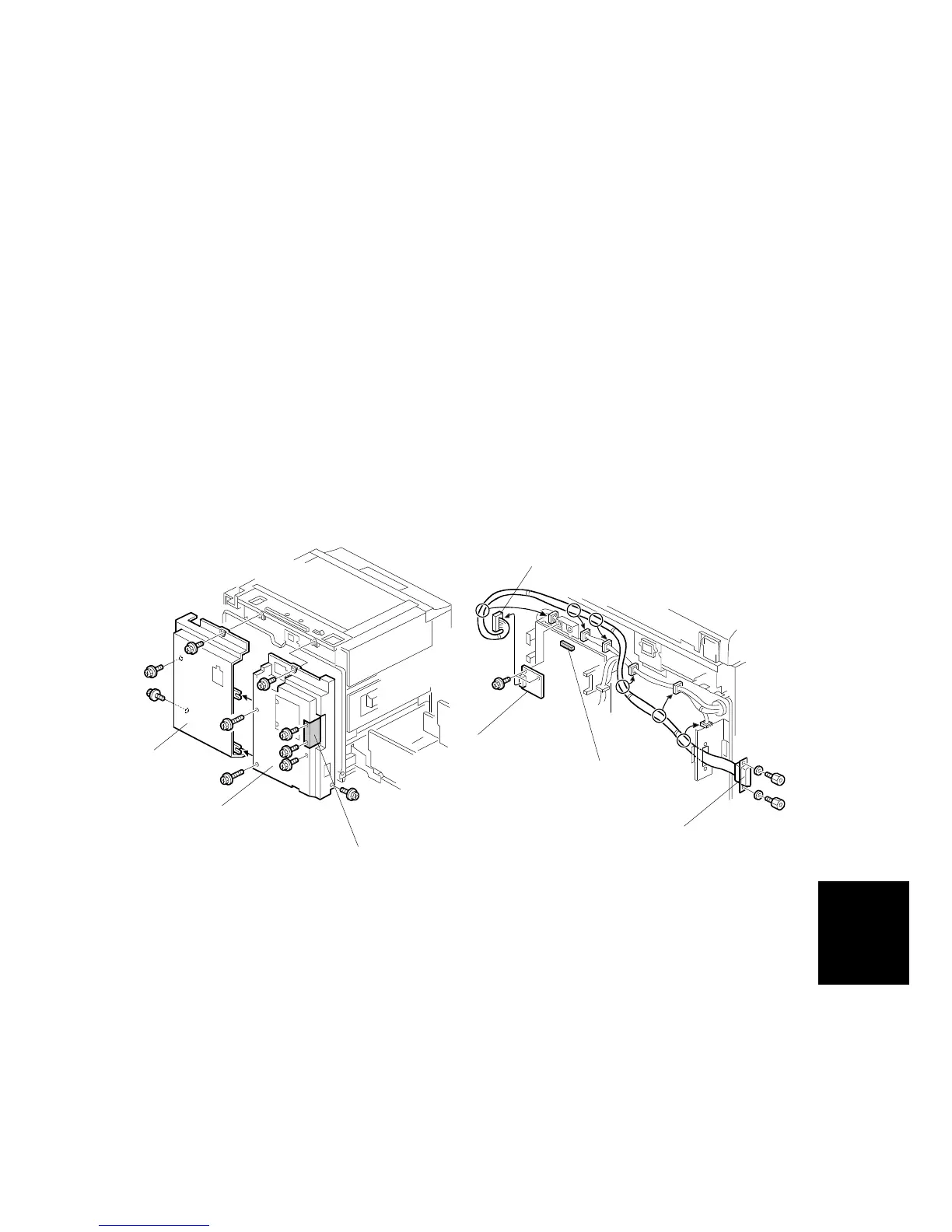
1. Remove the rear covers [A] [B] (8 screws).
2. Remove the I/F connector cover [C] (2 screws).
3. Install the I/F board [D] (accessories) in CN117 [E] on the MPU (2 screws).
4. Attach the cable [F] (accessories) to the connector bracket (2 screws) and
clamp the cable (6 clamps).
5. Connect the connector [G] at the opposite end to the I/F board.
6. Re-install the rear covers.
C238I041.WMF
C238I042.WMF
[A]
[B]
[C]
[D]
[E]
[F]
[G]