Chapter 8: Audio Module, Rev 1.1
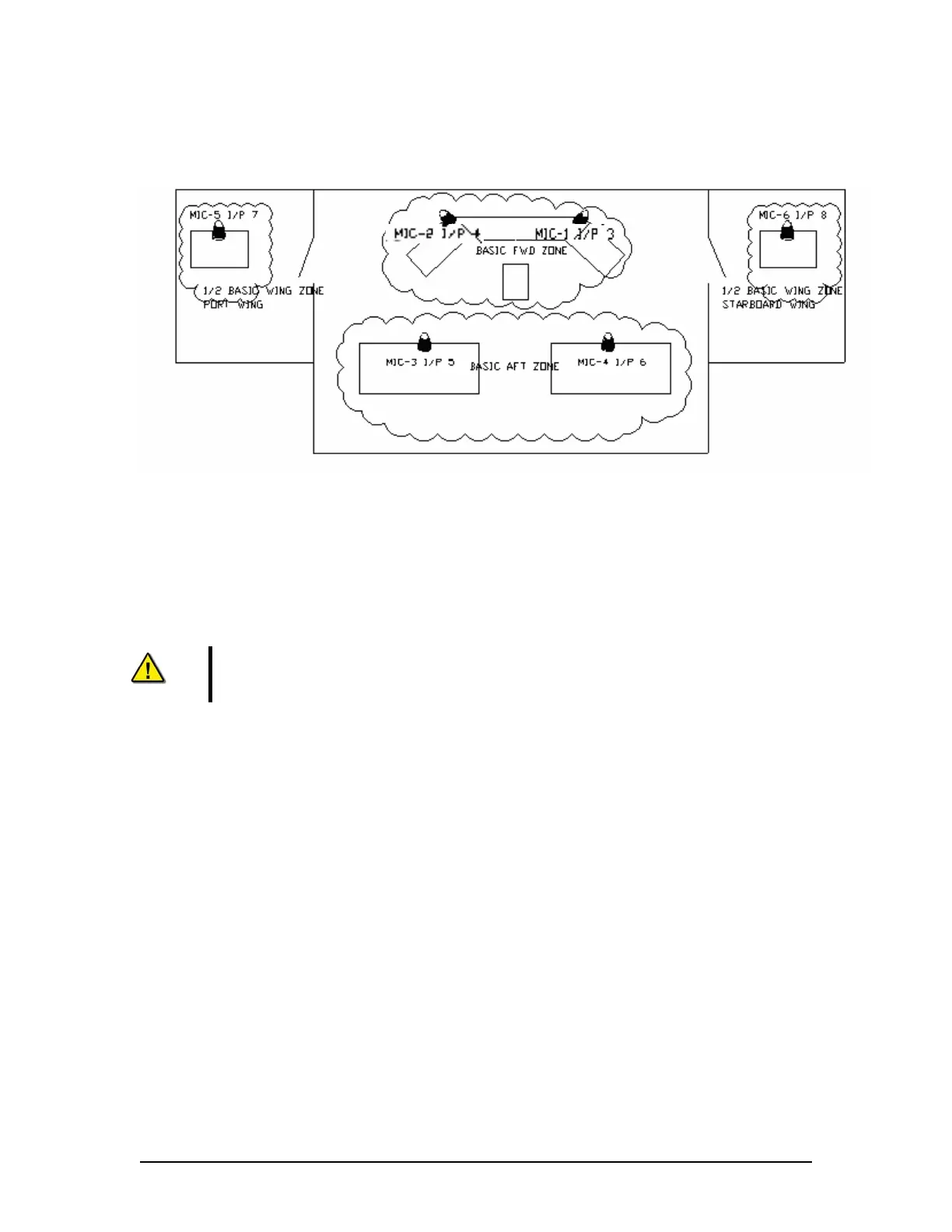
Figure 8-2: Typical VDR/SVDR Microphone Zoning (6 Microphones) below illustrates a bridge
zoning arrangement for the base VDR-100G3 system, complete with 6 microphones. The zoning
on this system provides 3 zones with 2 microphones each.
Figure 8-2: Typical VDR/SVDR Microphone Zoning (6 Microphones)
Automatic audio testing is performed at the same time across each zone (audio output channel)
when the VDR is in record mode. The buzzers connected to buzzer 1 outputs are simultaneously
activated during testing immediately followed by activation of buzzers connected to buzzer 2
outputs. For further explanation of microphone installation and testing (including a description of
zoning), see Section 8.1.3: Understanding Zones.
NOTE: The placement of microphones and the zoning of the bridge require
careful planning. The placement of the bridge audio recording must meet the
IEC 61996.2.and the MSC.163(78) standards.
VDR-100G3/G3S Installation Manual 06/10/2008
8-4