SINUS PENTA
PROGRAMMING GUIDE
204/486
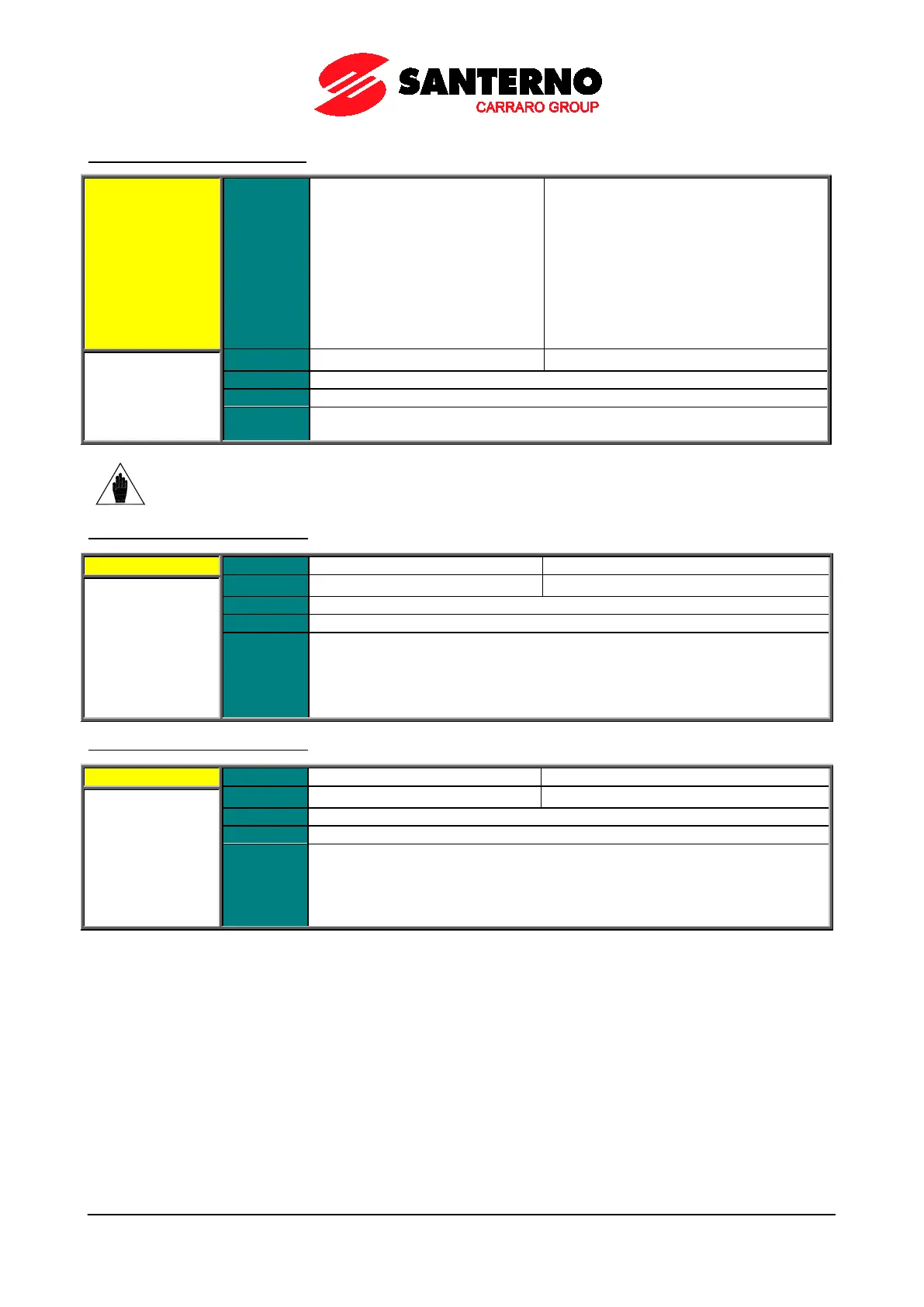
P270 MDO1: Digital Output Mode
P270 Range
0 ÷ 9
0: DISABLE
1: DIGITAL
2: DOUBLE DIGITAL
3: ANALOG
4: DOUBLE ANALOG
5: DOUBLE FULL
6: BRAKE
7: ABS BRAKE
8: ABS LIFT
9: PWM MODE
Function
This parameter defines the operating mode of digital output 1.
The different operating modes are described at the beginning of this chapter.
NOTE
MDO1 Digital output can be programmed only if the frequency output is not set up: P200
= Disable (see ANALOG AND FREQUENCY OUTPUTS MENU).
P271 MDO1: Selecting Variable A
Function
This parameter selects the digital signal used to calculate the value of
digital output.
It selects an analog variable used to calculate the value of MDO1
one of the “analog” operating modes is selected.
Digital signals and analog variables are detailed in See Table 48.
P272 MDO1: Selecting Variable B
Function
This parameter selects the second digital signal used to calculate the value of
MDO1 digital output.
It selects an analog variable used to calculate the value of MDO1
one of the “analog” operating modes is selected.
Digital signals and analog variables are detailed in See Table 48.