SINUS PENTA
PROGRAMMING GUIDE
338/486
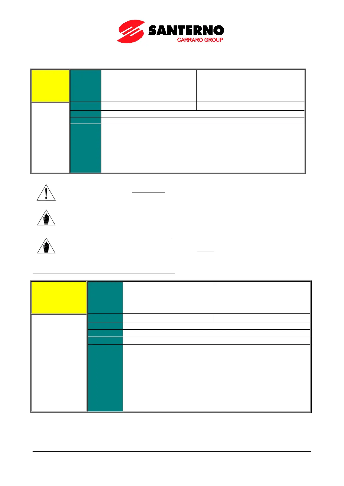
C169 JOG Input
C169 Range
0 ÷ 16
0 ÷ 24 if ES847 or ES870 is fitted
1 ÷ 8 → MDI1 ÷ MDI8
9 ÷ 12 → MPL1 ÷ MPL4
13 ÷ 16 → TFL1 ÷ TFL4
Function
When the JOG function is enabled, the motor rotates at low speed following slow
ramps which are manually controlled by the user only by means of the keys in keypad.
If the drive is enabled (ENABLE function
activated) but is not running, and if the JOG
terminal is enabled, the drive will run: the connected motor will accelerate following a
JOG ramp (P029) up to the JOG speed reference (P070
). On the other hand, if the
termi
nal is disabled, the drive will stop: the connected motor will decelerate to zero
speed following the JOG ramp (P029).
Reverse the direction of rotation of the active reference to reverse the JOG reference.
CAUTION
The motor starts running as soon as t
his terminal is activated (only if the drive is
enabled).
NOTE
The RUN function will override the JOG function.
Therefore, if the RUN function is active, the JOG function is ignored.
NOTE
If the motor is not running in SLAVE mode (torque reference i
reference), it can rotate at JOG speed when the user activates the JOG function.
In SLAVE mode, the JOG function is ignored
if the motor is still rotating due to an
active reference torque.
C169a Input for Selection of Speed Regulator Parameters
C169a
Range
0 ÷ 16
0 ÷ 24 if ES847 or ES870 is fitted
1 ÷ 8 → MDI1 ÷ MDI8
9 ÷ 12 → MPL1 ÷ MPL4
13 ÷ 16 → TFL1 ÷ TFL4
Function
This function allows switching between the two parameter sets pertaining to the
speed regulator.
The two pairs of parameters concerned are the same as the parameters
activating in case of automatic regulation based on the speed error (see
SPEED LOOP AND CURRENT BALANCING MENU).
For example, parameters P126/P128 and P125/P129 apply to Motor 1.
Always referring to Motor 1,
a low logic level of the input associated to the
selector keeps parameters P126/P128 active,
while a high logic level affects
speed regulation via parameters P125/P129.
This applies to Motor 2 and Motor 3 as well for parameters P136/P138 and
P135/P139 for Motor 2, or P146/P148 and P145/P149 for Motor 3.