USB on-the-go high-speed (OTG_HS) RM0033
1152/1381 RM0033 Rev 9
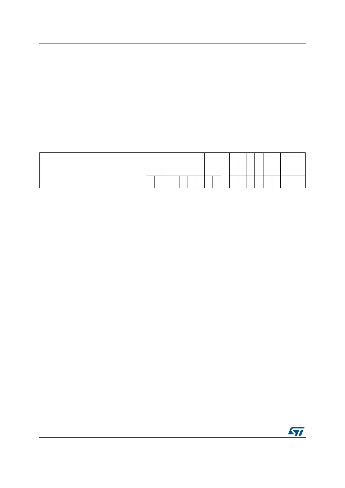
OTG_HS host port control and status register (OTG_HS_HPRT)
Address offset: 0x440
Reset value: 0x0000 0000
This register is available only in host mode. Currently, the OTG host supports only one port.
A single register holds USB port-related information such as USB reset, enable, suspend,
resume, connect status, and test mode for each port. It is shown in Figure 377. The rc_w1
bits in this register can trigger an interrupt to the application through the host port interrupt
bit of the core interrupt register (HPRTINT bit in OTG_HS_GINTSTS). On a Port Interrupt,
the application must read this register and clear the bit that caused the interrupt. For the
rc_w1 bits, the application must write a 1 to the bit to clear the interrupt.
313029282726252423222120191817161514131211109876 543210
Reserved
PSPD PTCTL
PPWR
PLSTS
Reserved
PRST
PSUSP
PRES
POCCHNG
POCA
PENCHNG
PENA
PCDET
PCSTS
r r rw rw rw rw rw r r rw rs rw
rc_
w1
r
rc_
w1
rc_
w0
rc_
w1
r
Bits 31:19 Reserved, must be kept at reset value.
Bits 18:17 PSPD: Port speed
Indicates the speed of the device attached to this port.
00: High speed
01: Full speed
10: Low speed
11: Reserved
Bits 16:13 PTCTL: Port test control
The application writes a nonzero value to this field to put the port into a Test mode, and the
corresponding pattern is signaled on the port.
0000: Test mode disabled
0001: Test_J mode
0010: Test_K mode
0011: Test_SE0_NAK mode
0100: Test_Packet mode
0101: Test_Force_Enable
Others: Reserved
Bit 12 PPWR: Port power
The application uses this field to control power to this port, and the core clears this bit on an
overcurrent condition.
0: Power off
1: Power on
Bits 11:10 PLSTS: Port line status
Indicates the current logic level USB data lines
Bit [10]: Logic level of OTG_HS_FS_DP
Bit [11]: Logic level of OTG_HS_FS_DM
Bit 9 Reserved, must be kept at reset value.
 Loading...


