Arm
®
CoreLink™ GIC-600AE Generic Interrupt Controller
Technical Reference Manual
Document ID: 101206_0003_04_en
Issue: 04
Components and configuration
This behavior means that writes must always make forward progress. The functionality of the ITS
means that there is a dependency between writes to the GITS_TRANSLATER register and reads to
memory, so one of the following conditions must be true:
•
The interconnect must allow forward progress of reads under all circumstances.
•
The GIC parameter dgi_mem_support must be set.
◦ This option provides support for routing all ITS translation-dependent traffic
through the ACE-Lite manager port on the Distributor which must have
free flowing access to memory. After this feature is configured, it must be
enabled at boot time. To enable this feature, write to GITS_FCTLR.DMA to
route the traffic through the Distributor.
◦ If dgi_mem_support is set, the ITS uses its ACE-Lite manager interface to
access the Command queue, and uses the Distributor ACE-Lite manager
interface to access tables.
◦ The ITS manager interface sends one single outstanding read and one single
outstanding write at a time to access the Command queue. The ARID signal
is 0x4 for the single outstanding read. The AWID signal is 0x0 for the single
outstanding write.
◦ Setting dgi_mem_support = 1 increases the width of the AxID signals on the
Distributor manager interface.
If neither condition is true, you must not use the configuration that Figure 3-3: ITS block on page
34 shows. This condition also applies to the CoreLink
™
CMN-600 Coherent Mesh Network,
if the I/O coherent Requesting Node (RN-I) is able to access the same I/O Home Node (HN-I) that
provides access to the PCIe Root Complex subordinate port. If the ITS is configured without a
bypass switch, then a bypass switch can still be used to provide ITS access to memory through a
different interconnect port, without merging the manager ports.
For more information, see 4.9 ITS on page 60.
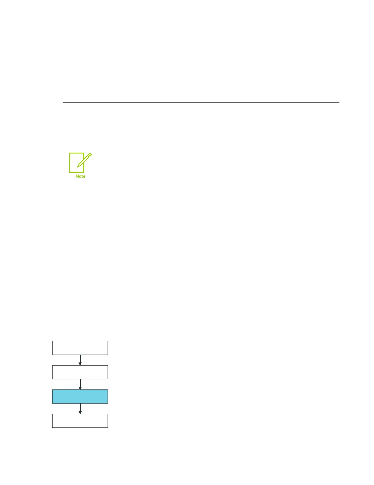
The following figure provides an example of the ITS integration process.
Figure 3-4: ITS integration
Copyright © 2018–2020, 2022 Arm Limited (or its affiliates). All rights reserved.
Non-Confidential
Page 35 of 268