DETAILED STEPS
Step 1
Connect one end of the RJ-45 cables to the serial RJ-45 port (CON) on the Cisco ASR 1000 Series Route Processor 1
(see Figure 77: Cisco ASR 1004 Router ASR 1000 Series Route Processor Console Port, on page 216).
Step 2
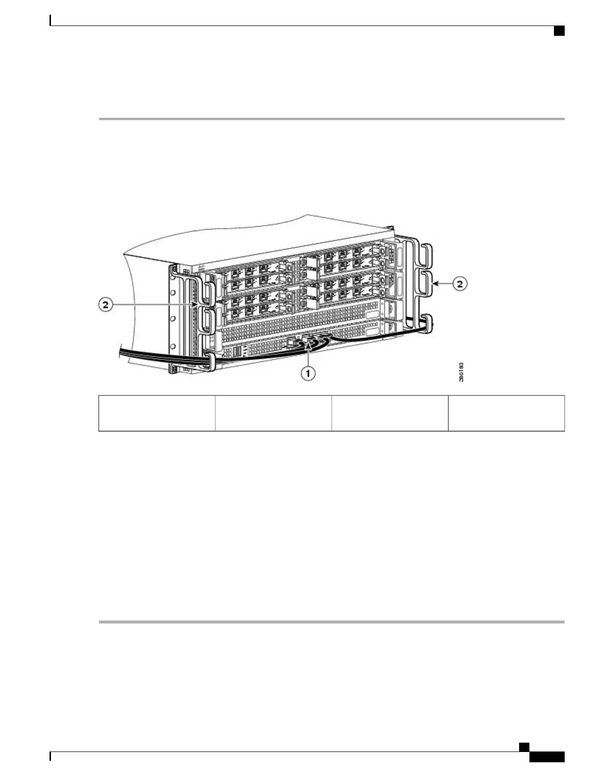
Run the cable up and through the cable-management bracket and connect the other end of the RJ-45 cable to the RJ-45
adapter (see the following image).
Figure 78: Cisco ASR 1004 Router Cable-Management Bracket
Cable-management bracket
U feature device
2BITS port connection1
Step 3
Connect the adapter to your video terminal to complete the cable connection.
Step 4
Power on your video terminal.
Step 5
Configure your video terminal to match the following default console port settings:
•
9600 baud
•
8 data bits
•
No parity generation or checking
•
1 stop bit
•
No flow control
Step 6
Go to the Connecting the Network Management and Signal System Cables, on page 218 to continue the installation.
Cisco ASR 1000 Series Router Hardware Installation Guide
217
Cisco ASR 1004 Router Overview and Installation
Connecting a Terminal to the Cisco ASR Series 1000 Route Processor Console Port
 Loading...


