EasyManuals Logo

Cisco ASR 1004 Hardware Installation Guide

Cisco ASR 1004
702 pages
To Next Page IconTo Next Page
To Previous Page IconTo Previous Page
Page #617 background imageLoading...
Page #617 background image
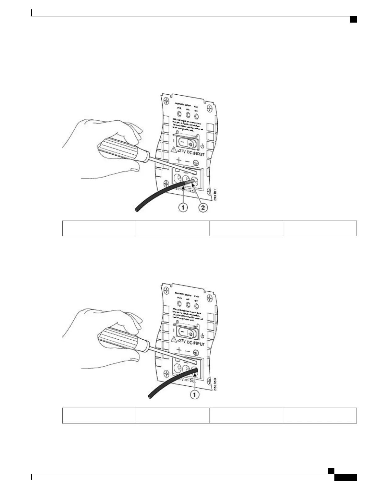
The following figure shows the +24 VDC power supply lead wire inserted into the terminal block.
Figure 288: Cisco ASR 1002 Router +24 VDC Power Supply Lead Wire Inserted into the Terminal Block
Copper wire2Lead wire insulation1
Step 8
Make certain no copper wire is visible as shown in the following figure which shows the lead wire fully inserted.
Figure 289: Cisco ASR 1002 Router +24 VDC Power Supply Lead Wire Fully Inserted
——
Fully-inserted lead wire1
Cisco ASR 1000 Series Router Hardware Installation Guide
583
Removing and Replacing FRUs from the Cisco ASR 1000 Series Routers
Removing and Replacing a +24 VDC Power Supply in Cisco ASR 1002 Router

Table of Contents

Other manuals for Cisco ASR 1004

Questions and Answers:

Question and Answer IconNeed help?

Do you have a question about the Cisco ASR 1004 and is the answer not in the manual?

Cisco ASR 1004 Specifications

General IconGeneral
Product TypeRouter
Form FactorRack-mountable
Rack Height2U
Forwarding CapacityUp to 20 Gbps
Total Number of PortsVaries by configuration
Number of Total Expansion Slots4
Product SeriesASR 1000
ModelASR 1004
Forwarding PerformanceUp to 20 Gbps
Operating SystemCisco IOS XE
Power SupplyDual
Route ProcessorASR 1000 Series Route Processor
Network Interface ModulesSFP, SFP+, Gigabit Ethernet, 10 Gigabit Ethernet
Interfaces/PortsVaries by configuration
Expansion Slot TypeSPA
Throughput20 Gbps
RedundancyPower supply, Route Processor
InterfacesGigabit Ethernet, 10 Gigabit Ethernet, SFP, SFP+
StorageUp to 64 GB Flash

Related product manuals