Step 11
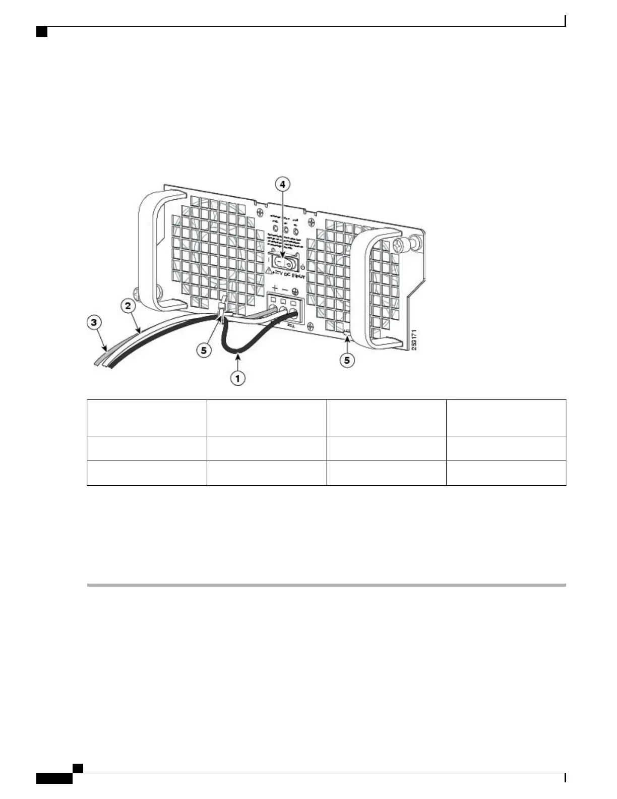
After inserting the ground wire leave an extra service loop in the ground lead to ensure that the ground lead is the last
lead to disconnect from the power supply if a great deal of strain is placed on all three leads as shown in the following
figure, callout 1.
Figure 292: Cisco ASR 1002 Router +24 VDC Power Supply Terminal Block Service Loop
+24 VDC power supply
Standby switch
4Ground lead wire with
service loop
1
Power supply tabs5Negative lead wire2
——
Positive lead wire3
Step 12
After tightening the receptacle screw for the ground, and leaving the extra service loop in the ground lead, use a cable
tie to secure the three leads to the power supply faceplate tie-wrap tab as shown in xref fig, callout 5.
Step 13
Turn on the branch source breaker.
Step 14
Place the power supply standby switch to the On (|) position. The power supply LEDs light when power is supplied to
the router.
What to Do Next
This completes the steps for installing the +24 VDC power supply in the Cisco ASR 1002 Router.
Cisco ASR 1000 Series Router Hardware Installation Guide
586
Removing and Replacing FRUs from the Cisco ASR 1000 Series Routers
Removing and Replacing a +24 VDC Power Supply in Cisco ASR 1002 Router
 Loading...


