Step 10
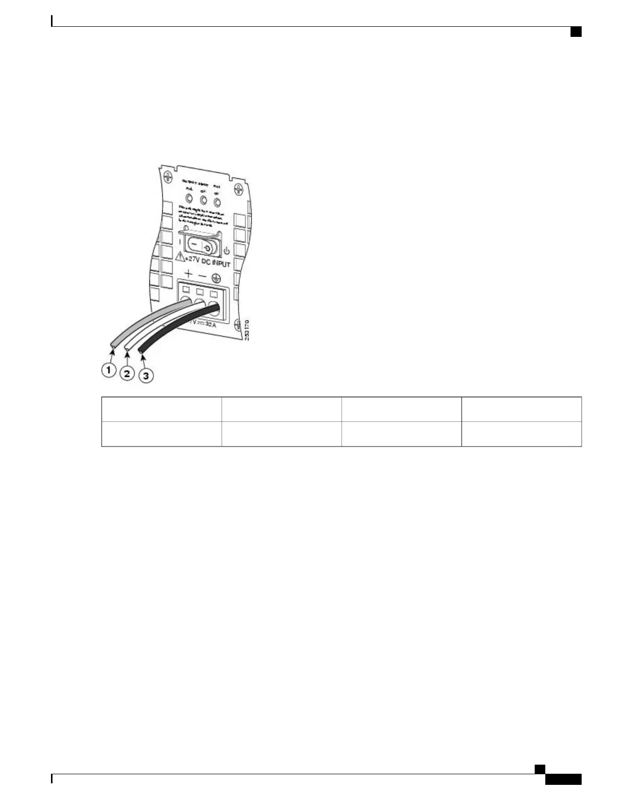
Repeat Steps 5 through Step 10 for each lead wire. The following figure shows the leads wires installed in the terminal
block.
Figure 291: Cisco +24 VDC Power Supply Terminal Block with Lead Wires Installed
Ground lead wire3Positive lead wire1
——
Negative lead wire2
Make sure the stripped end of each lead wire is twisted tightly together. This makes insertion easier. Then make
certain the entire lead wire is inserted all the way into its receptacle. If any exposed wire at the stripped end of
a lead is visible after inserting the lead into its receptacle, remove the lead from the receptacle, use the wire
stripper to cut the stripped end of the lead, and then reinsert.
Note
When securing the ground, positive, and negative +24 VDC-input leads to the power supply faceplate, leave
extra service loop in the ground (GND) lead to ensure that the ground lead is the last lead wire to disconnect
from the power supply if a great deal of strain is placed on all three leads.
Caution
Cisco ASR 1000 Series Router Hardware Installation Guide
585
Removing and Replacing FRUs from the Cisco ASR 1000 Series Routers
Removing and Replacing a +24 VDC Power Supply in Cisco ASR 1002 Router
 Loading...


