Step 9
Repeat Step 6 through Step 8 for the remaining two DC input power source wires, the positive lead wire and the negative
lead wire (see the following figure).
Figure 310: Inserting the DC Power Supply Terminal Block Plug in the Block Header
DC power supply ground
lead wire
3DC power supply negative
(-) lead wire
1
——
DC power supply positive
(+) lead wire
2
Secure the wires coming in from the terminal block plug so that they cannot be disturbed by casual contact.Caution
Step 10
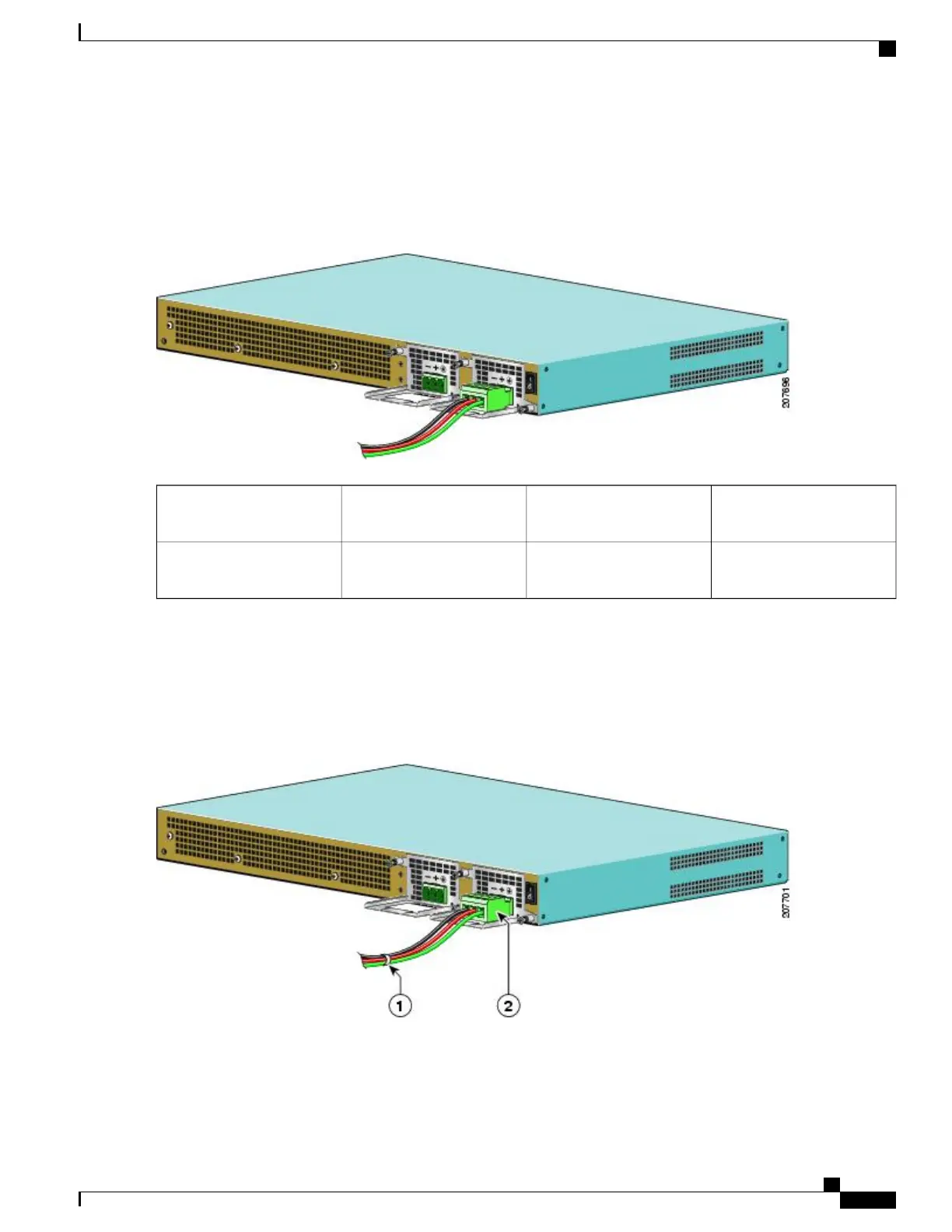
Use a tie wrap to secure the wires to the rack, so that the wires are not pulled from the terminal block plug by casual
contact. Make sure the tie wrap allows for some slack in the ground wire as shown in the following figure.
Figure 311: Complete DC Terminal Block Plug Insertion and Secure Tie Wrap
Cisco ASR 1000 Series Router Hardware Installation Guide
611
Removing and Replacing FRUs from the Cisco ASR 1000 Series Routers
Removing DC Input Power from the Cisco ASR 1001 Router
 Loading...


