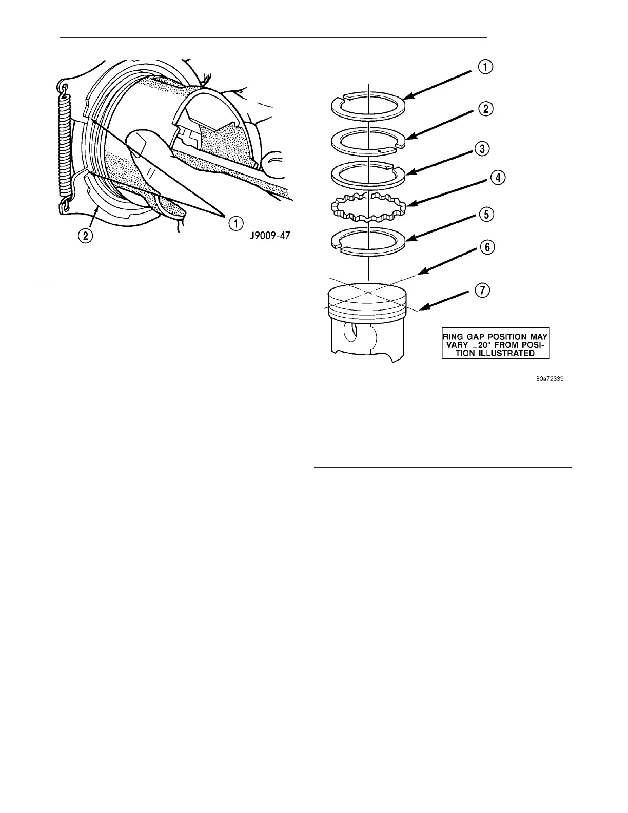
Ring Gap Orientation
• Position the gaps on the piston as shown (Fig.
46).
• Oil spacer - Gap on cent er lin e of piston skir t.
• Oil rails - ga p 180° apa rt on centerline of piston
pin bore.
• No. 2 Compression r ing - Gap 120° from t op oil
rail gap.
• No. 1 Compression ring - Gap 120° from No. 2
compression r ing gap.
VIBRATION DAMPER
REMOVAL
NOTE: If vehicle is equipped with the additional air
conditioner compressor, you must first remove the
coolant module and additional A/C belt then use
damper puller # 9544.
(1) Disconn ect nega tive battery cable.
(2) Remove accessory dr ive belt (Refer to 7 -
COOLING/ACCESSORY DRIVE/DRIVE BEL TS -
REMOVAL).
(3) In st all retainin g lock for crankshaft/rin g gear
(Fig. 47).
(4) Remove cranksha ft cen ter bolt a nd wa sh er
(Fig. 47).
NOTE: If hub of belt pulley/vibration damper is
tight, use puller # 8940 to remove. DO NOT tilt
puller when in use. Grooves of the puller must
mesh fully into the slots of the belt pulley.
Fig. 45 Compression Ring Installation
1 - COMPRESSION RING
2 - RING EXPANDER RECOMMENDED
Fig. 46 Ring Gap Orientation
1 - TOP COMPRESSION RING
2 - BOTTOM COMPRESSION RING
3 - TOP OIL CONTROL RAIL
4 - OIL RAIL SPACER
5 - BOTTOM OIL CONTROL RAIL
6 - IMAGINARY LINE PARALLEL TO PISTON PIN
7 - IMAGINARY LINE THROUGH CENTER OF PISTON SKIRT
VA ENGINE 9 - 53