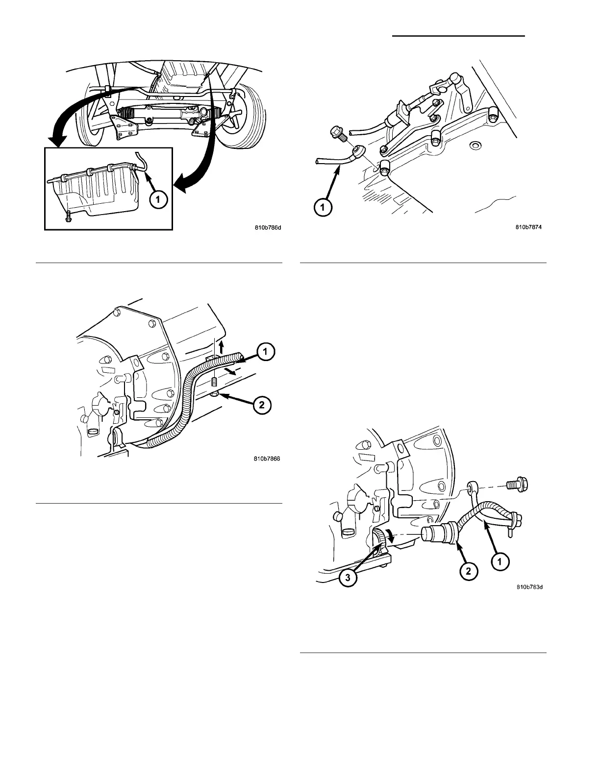
(10) Disconn ect the tr ansmission elect rical connec-
tor (2) (Fig. 32) from transmission a nd hang to th e
side. Turn sealing ring (3) coun terclockwise and dis-
connect plug con nection (2).
(11) Detach shift cable at tr ansmission.
(a) Un latch ba ll socket la tch (Fig. 33) of cable.
(b) Unclip shift cable retainer from reta iner
bracket. Wh en pullin g out cable, pr ess together
hooks of shift cable retainer at the points sh own
(arrows).
(c) Pull shift cable out of ba ll socket. Ball socket
can rem ain on tr ansmission lever.
Fig. 29 Cooler Line Supports
1 - COOLER LINES
Fig. 30 Cable Support
1 - CABLE
2 - BOLT
Fig. 31 Driver’s Side Cooler Line
1 - COOLER LINE
Fig. 32 Transmission Electrical Connector and
Cooler Line
1 - COOLER LINE
2 - TRANSMISSION ELECTRICAL CONNECTOR
3 - SEALING RING
21 - 44 AUTOMATIC TRANSMISSION NAG1 - SERVICE INFORMATION VA