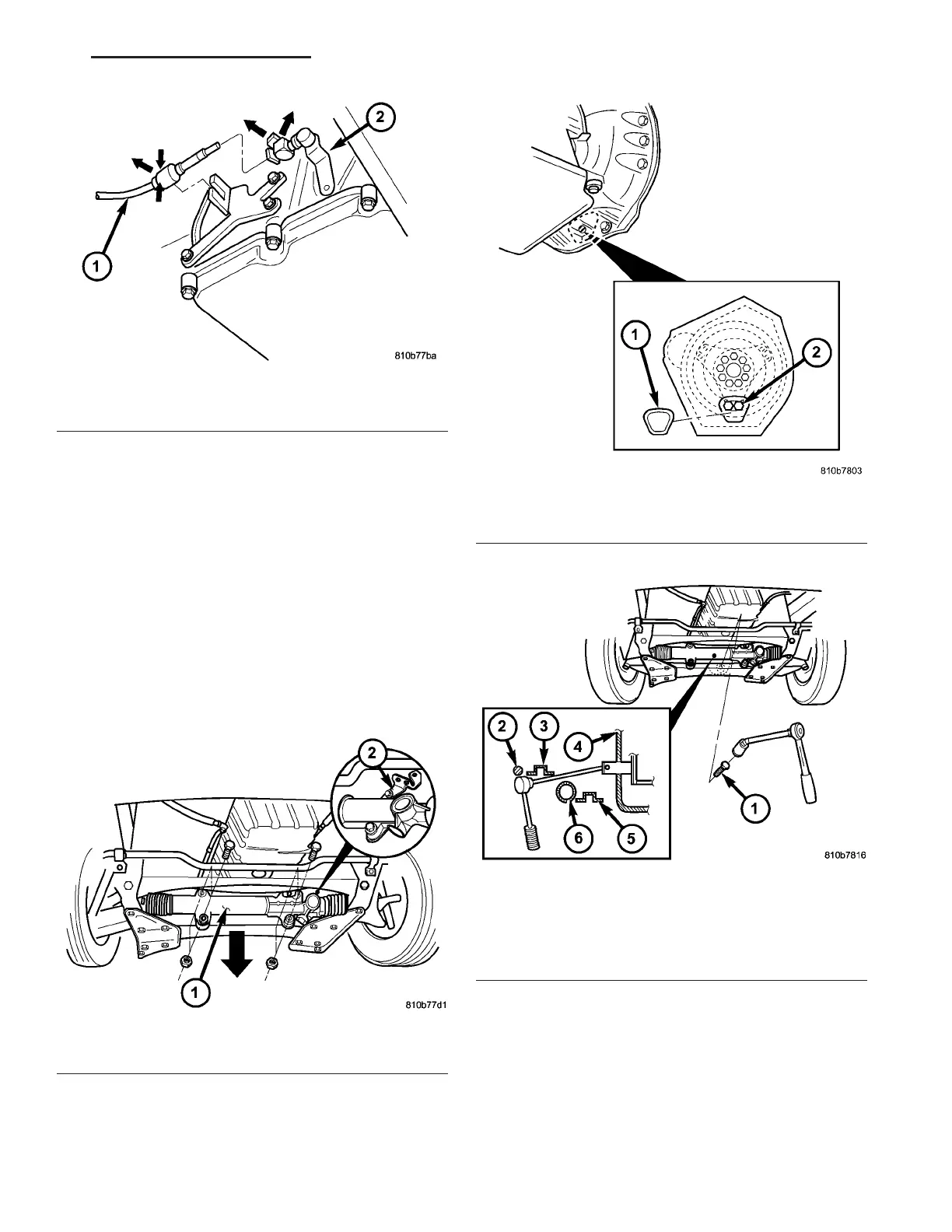
(12) Remove th e torque converter bolts.
(a) Remove the steerin g gear (1) (F ig. 34) from
the ch assis crossmem ber.
(b) Lower th e steering gea r (1) (Fig. 34) down-
wa r ds .
(c) Remove the plastic torqu e con vert er access
cover (1) (F ig. 35) at back of en gin e flange.
(d) Rot ate en gine by hand until bolts (2) (Fig.
35) are in fron t of open ing. Rotate engine for wards
at cranksha ft.
(e) To remove bolts, position a r atchet with long
extension and joint nu t as shown (Fig. 36).
(f) Remove t he two bolts (2) (Fig. 35) at each of
the three locations a t circu mference of driving
plat e.
(13) Remove torque convert er dra in plug and drain
automatic tran sm ission oil into a clean con tainer. Re-
insta ll the drain plug and t orque the plug to 14 N·m
(130 in.lbs.).
(14) Support en gin e. Insert wooden block between
oil pa n and fron t chassis crossmember beam.
(15) Remove vent h ose br acket and tie back to one
side.
Fig. 33 Shift Cable at Transmission
1 - SHIFT CABLE
2 - TRANSMISSION SHIFT LEVER
Fig. 34 Steering Gear
1 - STEERING GEAR
2 - BRACKET
Fig. 35 Torque Converter Access Cover
1 - TORQUE CONVERTER ACCESS COVER
2 - BOLT
Fig. 36 Torque Converter Bolts Access
1 - BOLT
2 - STABILIZER BAR
3 - REINFORCEMENT PLATE
4 - OPENING
5 - CHASSIS CROSSMEMBER
6 - STEERING GEAR
VA AUTOMATIC TRANSMISSION NAG1 - SERVICE INFORMATION 21 - 45