NOTE: During the measurement the snap ring (7)
(Fig. 49) must contact the upper bearing surface of
the groove in the outer multiple-disc carrier (8).
NOTE: Pay attention to sequence of discs. If the
original clutch discs are reused, be sure to return
the disc identified on disassembly as belonging on
top of the spring washer (4) to its original location.
Place new friction multiple-discs in ATF fluid for
one hour before installing.
(4) In sert and m easure spring wash er (4) (Fig. 49)
and multiple-disc pa ck B3 (2, 6).
(a) Put multiple-discs for mu ltiple-disc holding
clutch B3 together in the sequence shown in the
illustr ation and insert individua lly.
(b)
CAUTION: Apply only light pressure (less than 10 N
(3 lbs.) of force) to the clutch pack when measuring
the clutch clearance with the feeler gauge. Applying
excessive force to the clutch will give an incorrect
reading and lead to a transmission failure.Using a
feeler gauge, determine the play “L” at three points
between the snap ring (7) and outer multiple-disc
(1). B3 clutch clearance should be 1.0-1.4 mm
(0.039-0.055 in.). Adjust the clearance as necessary.
(c) Adjust with snap-ring (7), if necessary. Sn ap-
rings are available in thickn esses of 3.2 m m (0.126
in.), 3.5 mm (0.138 in.), 3.8 m m (0.150 in.), 4.1 mm
(0.162 in.), 4.4 mm (0.173 in.), and 4.7 mm (0.185
in.).
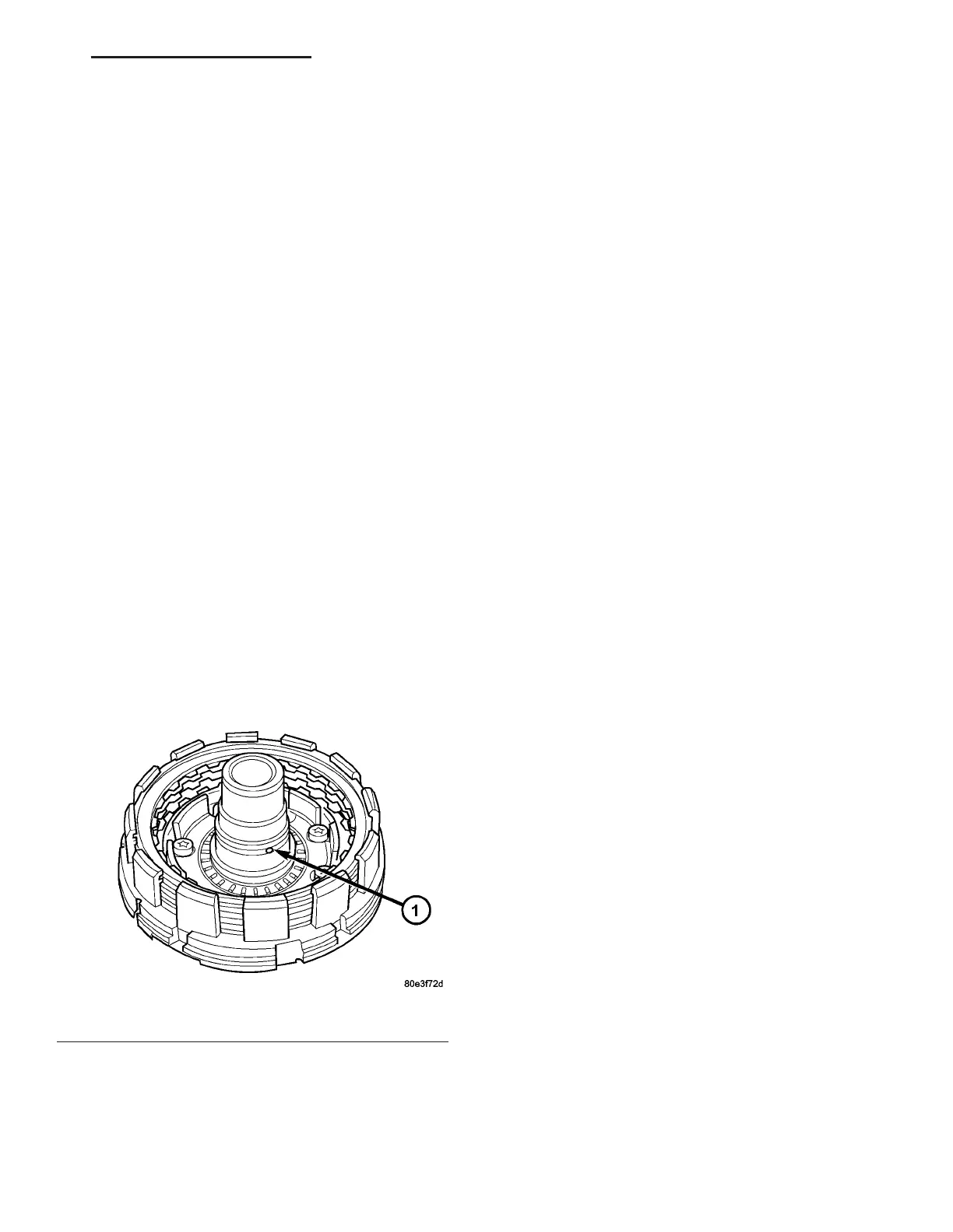
(5) Check th at t he K1 clutch feed h ole (1) (Fig. 50)
in the inner h ub of clu tch B1 is free before installing
clutch B1.
Fig. 50 Check K1 Feed Hole
1 - K1 CLUTCH FEED HOLE
VA AUTOMATIC TRANSMISSION NAG1 - SERVICE INFORMATION 21 - 53