(18) Using gr ease, in st all bot h Teflon rings in th e
groove at the r ear of th e output sha ft so that the
joint stays together.
(19) Mount tr ansmission housing on conver ter
housin g.
(20) Screw in Torx socket bolts th rough the tr ans-
mission housing into t he conver ter housin g. Tighten
the bolts t o 20 N·m (177 in.lbs.).
(21) Measure end-pla y between pa rk pawl gea r
and grooved ball bear ing in order to select the proper
gear tra in end-pla y shim.
(22) Pla ce Gauge Bar 631 1 (1) on tra nsmission
housin g. Using a depth gauge, measur e from the
gau ge bar (1) to t he pa rking lock gear (2) (Fig. 54).
(23) Using a depth ga uge, mea su re from the
Gauge Bar 6311 (1) to the contact surface of the out -
pu t sh aft bear ing (2) in the transmission housing.
(Fig. 55)
(24) Subtr act th e fir st figu re from the secon d fig-
ure to det ermine the cur rent end-play of the tran s-
mission . Select a shim such t hat th e end-play will be
0.3-0.5 mm (0.012-0.020 in.). Shims are available in
thicknesses of 0.2 mm (0.008 in.), 0.3 mm (0.012 in.),
0.4 mm (0.016 in.), an d 0.5 mm (0.020 in .).
(25) Install the select ed end-pla y shim.
(26) Screw in Torx socket bolts throu gh t he con-
vert er housing into the tra nsmission housing.
Tighten t he bolts to 20 N·m (177 in.lbs.).
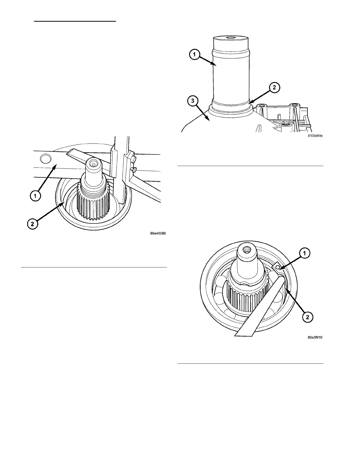
(27) Install output sh aft bearing (2) in r ear trans-
mission housing. Using Bearing Insta ller 9287 (1)
(Fig. 56), inst all t he output sha ft bearing (2) into the
transmission housing. Th e c l o s e d s i d e o f the p l a s -
tic cage must point tow ards the parking lock
gear.
(28) Install the retaining ring (1) (Fig. 57). Ensure
that th e ret ain ing ring is sea ted correct ly in the
groove.
(29) Check tha t t here is no pla y between the bear-
ing and the ret ain ing rin g using feeler gauge.
(30) Ther e m ust be n o play between the r etaining
ring and the bea ring. If th e ring can not be installed,
athinnerringmustbeused.Ifthereisplaybetween
the ring a nd t he bear ing, a thicker ring must be
Fig. 55 Measure From Transmission Housing To
Rear Bearing Contact Surface
1 - GAUGE BAR 6311
2 - OUTPUT SHAFT BEARING CONTACT SURFACE
Fig. 56 Install Output Shaft Bearing
1 - BEARING INSTALLER 9287
2 - BEARING
3 - TRANSMISSION CASE
Fig. 57 Install Rear Output Shaft Retaining Ring
1 - RETAINING RING
2 - OUTPUT SHAFT BEARING
VA AUTOMATIC TRANSMISSION NAG1 - SERVICE INFORMATION 21 - 57