insta lled. Ret ain ing rings are available in thick-
nesses of 2.0 mm (0.079 in.), 2.1 mm (0.083 in.), an d
2.2 mm (0.087 in.).
(31) Rotate th e tr ansmission so th at the bellhous-
ing is pointed upward an d ensuring that the output
sh aft is allowed t o move freely.
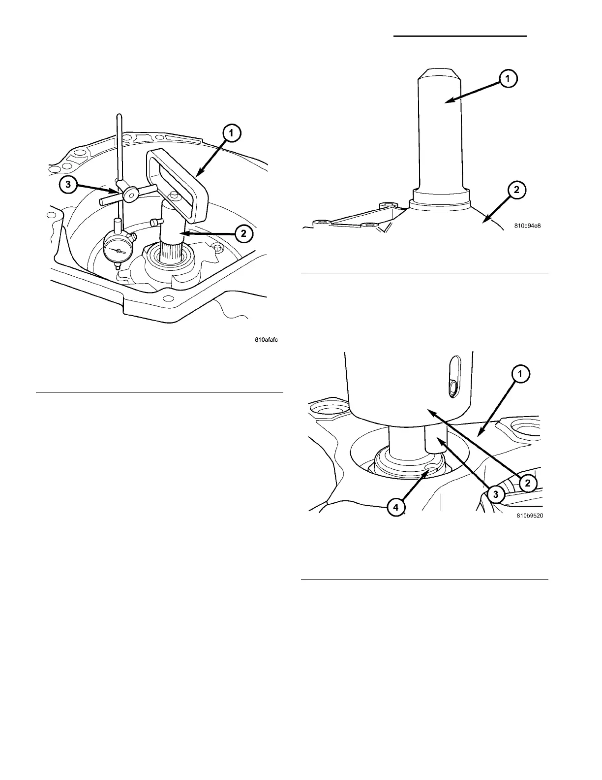
(32) Measure in pu t shaft end-pla y (Fig. 58).
NOTE: If end-play is incorrect, transmission is
incorrectly assembled, or the geartrain end-play
shim is incorrect. The geartrain end-play shim is
selective.
(a) Atta ch Adapter 8266-18 (2) to Ha ndle 8266-8
(1).
(b) Attach dial indicator C-3339 (3) to Han dle
8266-8 (1).
(c) Install the assembled tool onto the input
sh aft of th e t ransmission an d tight en t he reta ining
scr ew on Adapter 8266-18 to secure it to the input
sh aft.
(d) Position th e dial in dicator plunger aga inst a
flat spot on the oil pump a nd zero t he dial indica-
tor.
(e) Move input shaft in and ou t an d record rea d-
ing. End pla y sh ould be 0.3-0.5 mm (0.012-0.020
in.). Adjust as necessa ry.
(33) Install the out pu t shaft washer onto th e ou t-
pu t shaft.
(34) Install a new transmission rear seal into the
transmission ca se with Seal Insta ller 8902A (1) (Fig.
59).
(35) Pla ce th e tra nsmission in PARK to prepa re for
the insta lla tion of t he out pu t sh aft nut .
(36) Install the propeller shaft fla nge onto the out-
pu t sha ft an d install an new flange nut. Tigh ten the
flan ge nu t to 200 N·m (147.5 ft.lbs.).
(37) Pla ce the Stakin g Tool 9078 (2) an d Driver
Handle C-4171 onto the ou tput sha ft.
(38) Rotate the Staking Tool 9078 (2) un til the
alignm ent pin (3) engages th e outpu t sh aft notch (4)
(Fig. 60).
Fig. 58 Checking Input Shaft End Play
1 - TOOL 8266-8
2 - TOOL 8266-18
3 - TOOL C-3339
Fig. 59 Install Output Shaft Seal
1 - SEAL INSTALLER 8902A
2 - TRANSMISSION CASE
Fig. 60 Align Staking Tool 9078
1 - PROPELLER SHAFT FLANGE
2 - STAKING TOOL 9078
3 - ALIGNMENT PIN
4 - OUTPUT SHAFT NOTCH
21 - 58 AUTOMATIC TRANSMISSION NAG1 - SERVICE INFORMATION VA