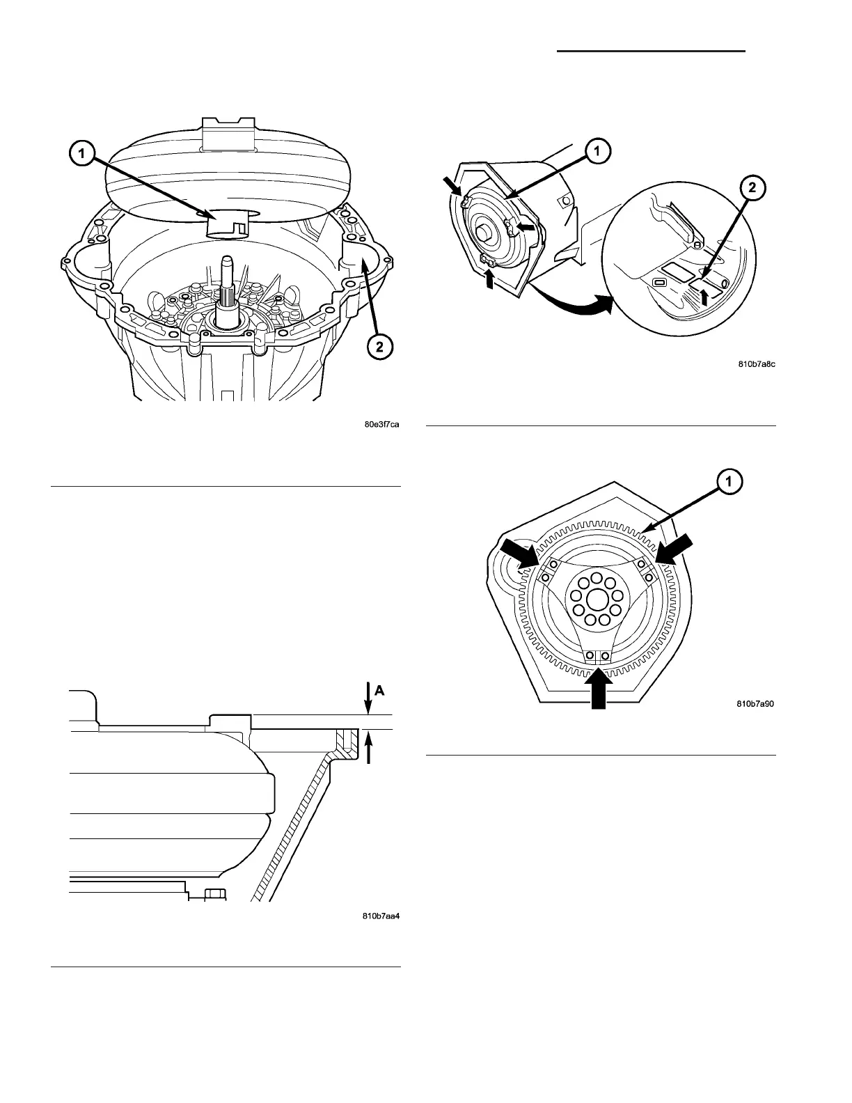
(45) Install the torqu e converter (Fig. 63).
INSTALLATION
(1) Coat outside of the torque conver ter hub with
long-term grease, insta ll the torqu e converter in to
the t ransmission.
(2) Measur e dist ance “A” (Fig. 64) from torque con-
vert er to t ran smission housing. If the tor que con-
vert er is properly installed, distance “A” will be 55
mm (2.17 in.).
(3) Move the torque conver ter (1) (Fig. 65) to
sh own posit ion. Check position of tor que converter
through hou sing openin g (2) when insta lling tra ns-
mission .
(4) Move drivin g plate (1) (Fig. 66) to shown posi-
tion.
(5) Ensur e the dowel pin s a re in st alled in their
correct posit ion at the transmission housing flan ge.
(6) Pla ce t ransmission onto a hydrau lic tran smis-
sion jack and r aise the tr ansmission int o position .
Secure t ran smission on hydrau lic jack wit h a stra p
or ask a n assistant to hold it.
(7) Move the tra nsmission int o position on the
dowel pins and install two bolts (A, B) (Fig. 67) on
the top of th e tr ansmission. Torqu e the bolts to 38
N·m (28 ft.lbs.).
(8) In st all the bolt t o hose th e vent h ose br acket to
the transm ission. Torque t he bolt to 38 N·m (28
ft.lbs.).
(9) In st all the bolt to hold the gr ound stra p to the
transmission . Torqu e the bolt to 38 N·m (28 ft.lbs.).
Fig. 63 Install Torque Converter
1 - TORQUE CONVERTER
2 - CONVERTER HOUSING
Fig. 64 Torque Converter Installation Depth
A - TORQUE CONVERTER INSTALLED DISTANCE
Fig. 65 Position Torque Converter as Shown
1 - TORQUE CONVERTER
2 - INSPECTION OPENING
Fig. 66 Position Driveplate as Shown
1 - DRIVEPLATE
21 - 60 AUTOMATIC TRANSMISSION NAG1 - SERVICE INFORMATION VA