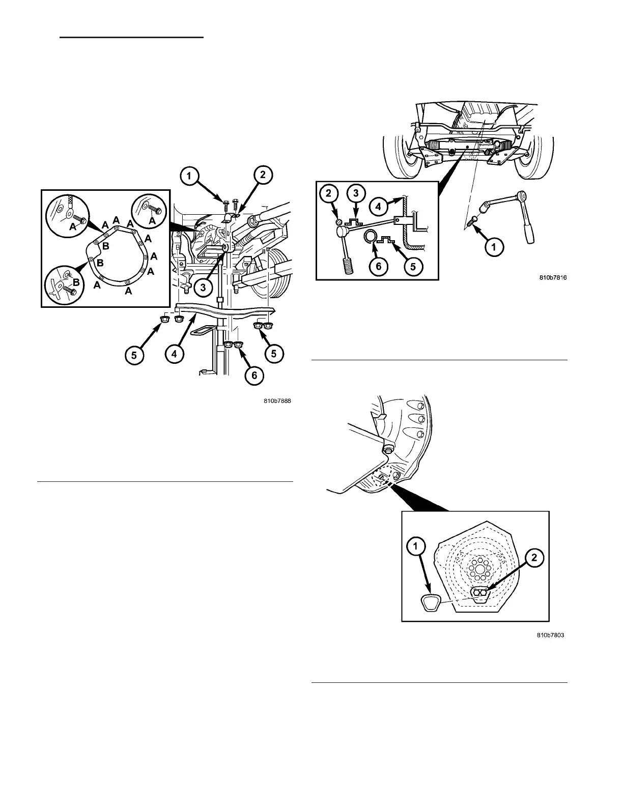
(10) Install bolts (A) (Fig. 67) on underside of
transmission . Torqu e the bolts t o 38 N·m (28 ft.lbs.).
(11) In st all rear engine cr oss member (4) (Fig. 67).
First install th e nu ts (5) at the outside en ds of the
engine crossmem ber. Then insta ll the bolts (1) of the
transmission moun t. Torque t he bolts and nuts to 45
N·m (33 ft.lbs.).
(12) Remove th e wooden block support ing the
engine a nd rem ove the hydr aulic jack.
(13) Install the torqu e converter bolts.
(a) Install the first pair bolts (2) (Fig. 68) at cir-
cumfer ence of dr iving plate sn ug on ly.
(b) To install bolts, position a ra tchet with long
extension and joint nu t as shown.
(c) Rot ate en gine by han d un til t he next pair of
bolts (2) are in fron t of openin g. Rot ate engine for-
wards a t cran kshaft. Install th e next pair of bolts
sn ug on ly.
(d) Rot ate engine by h and until th e final pa ir of
bolts (2) are in fron t of openin g. Rot ate engine for-
wards at cr ankshaft. Insta ll a nd t orque the bolts to
50 N·m (37 ft.lbs.).
(e) Rotat e engine by hand a nd tighten the first
two bolt pair s t o 50 N·m (37 ft.lbs.).
(f) Install t he plastic torque conver ter access
cover (1) (Fig. 69) to th e back of the en gin e flan ge.
(g) Install the steerin g gear (1) (Fig. 70) ont o t he
chassis crossmember. Tighten bot h st eerin g gear
bolts first t o 25 N·m (18.5 ft.lbs.). Tigh ten bot h
st eering gear bolt s next to 45 N·m (33 ft.lbs.).
Tighten bot h steerin g gear bolts n ext an addit iona l
90°.
Fig. 67 Support Transmission and Install Bolts
1 - BOLT, TRANSMISSION MOUNT
2 - UPPER SHELL FOR TRANSMISSION MOUNT
3 - TRANSMISSION MOUNT
4 - CROSSMEMBER
5 - NUT, ENGINE CROSSMEMBER
6 - NUT, TRANSMISSION SUPPORT
Fig. 68 Torque Converter Bolts
1 - BOLT
2 - STABILIZER BAR
3 - REINFORCEMENT PLATE
4 - OPENING
5 - CHASSIS CROSSMEMBER
6 - STEERING GEAR
Fig. 69 Torque Converter Access Cover
1 - TORQUE CONVERTER ACCESS COVER
2 - BOLT
VA AUTOMATIC TRANSMISSION NAG1 - SERVICE INFORMATION 21 - 61