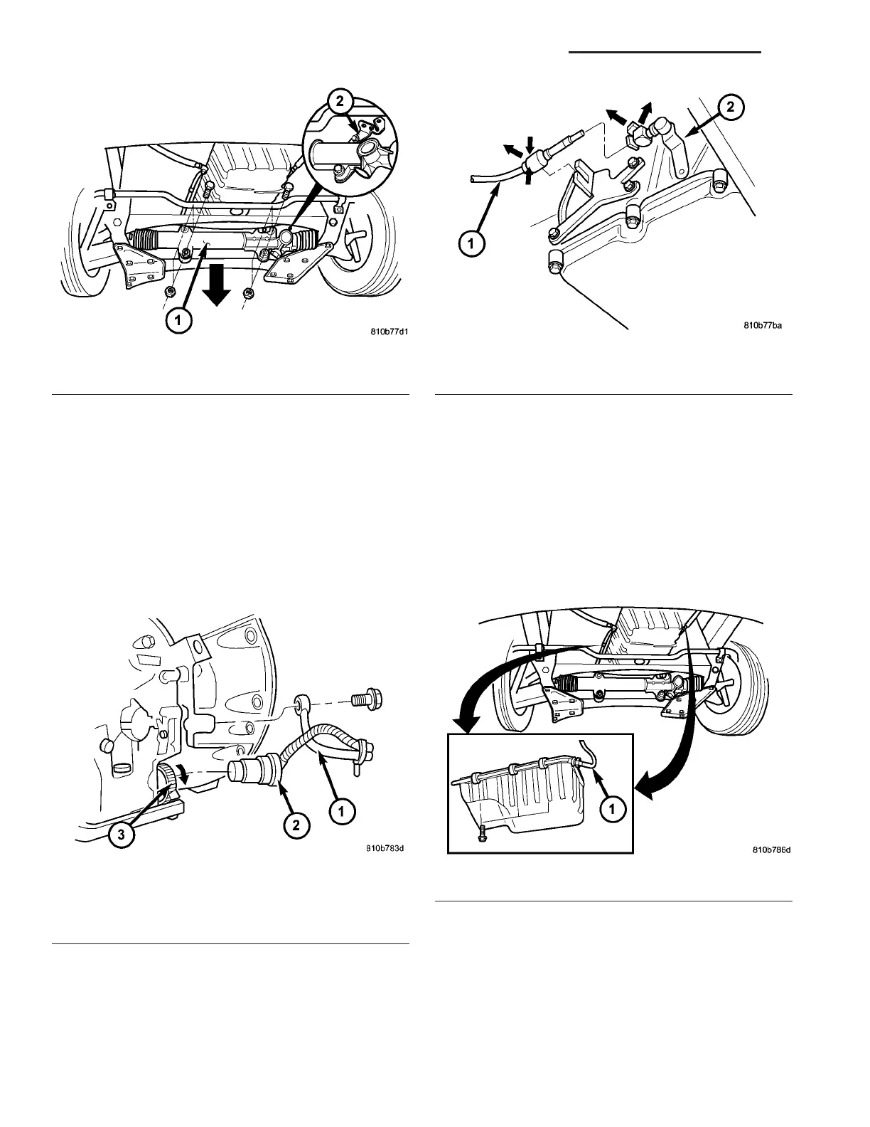
(14) Install the tra nsmission electrical connector
(2) (Fig. 71) from tran sm ission and hang to the side.
Turn sealing ring (3) clockwise a nd conn ect plug con-
nection (2).
(15) Install t he shift cable (Fig. 72) t o the trans-
mission .
(a) Push shift cable onto t he tran sm ission shift
lever ball socket.
(b) Latch ball socket latch of cable.
(c) Clip shift cable ret ainer into reta iner
bracket.
(16) Install the cooler lines t o the tra nsmission.
(a) Install the br ackets for th e oil cooler feed an d
retu rn lines (1) (Fig. 73) on to the en gin e oil pan
flan ge. Detail sh ows right side of motor. Position is
mirrored for th e left side of engine.
(b) Attach the bra cket for the cable retainer (4)
(Fig. 74) to the t hrea ded sh ank of a engine oil pan
bolt (5).
(c) Install th e bolts t o hold th e oil cooler lin es (6)
to the left (Fig. 75) and right sides of tr ansmission.
Torque the bolts t o 34 N·m (25 ft.lbs.).
Fig. 70 Install Steering Gear
1 - STEERING GEAR
2 - BRACKET
Fig. 71 Transmission Electrical Connector and
Cooler Line
1 - COOLER LINE
2 - TRANSMISSION ELECTRICAL CONNECTOR
3 - SEALING RING
Fig. 72 Shift Cable at Transmission
1 - SHIFT CABLE
2 - TRANSMISSION SHIFT LEVER
Fig. 73 Cooler Line Supports
1 - COOLER LINES
21 - 62 AUTOMATIC TRANSMISSION NAG1 - SERVICE INFORMATION VA