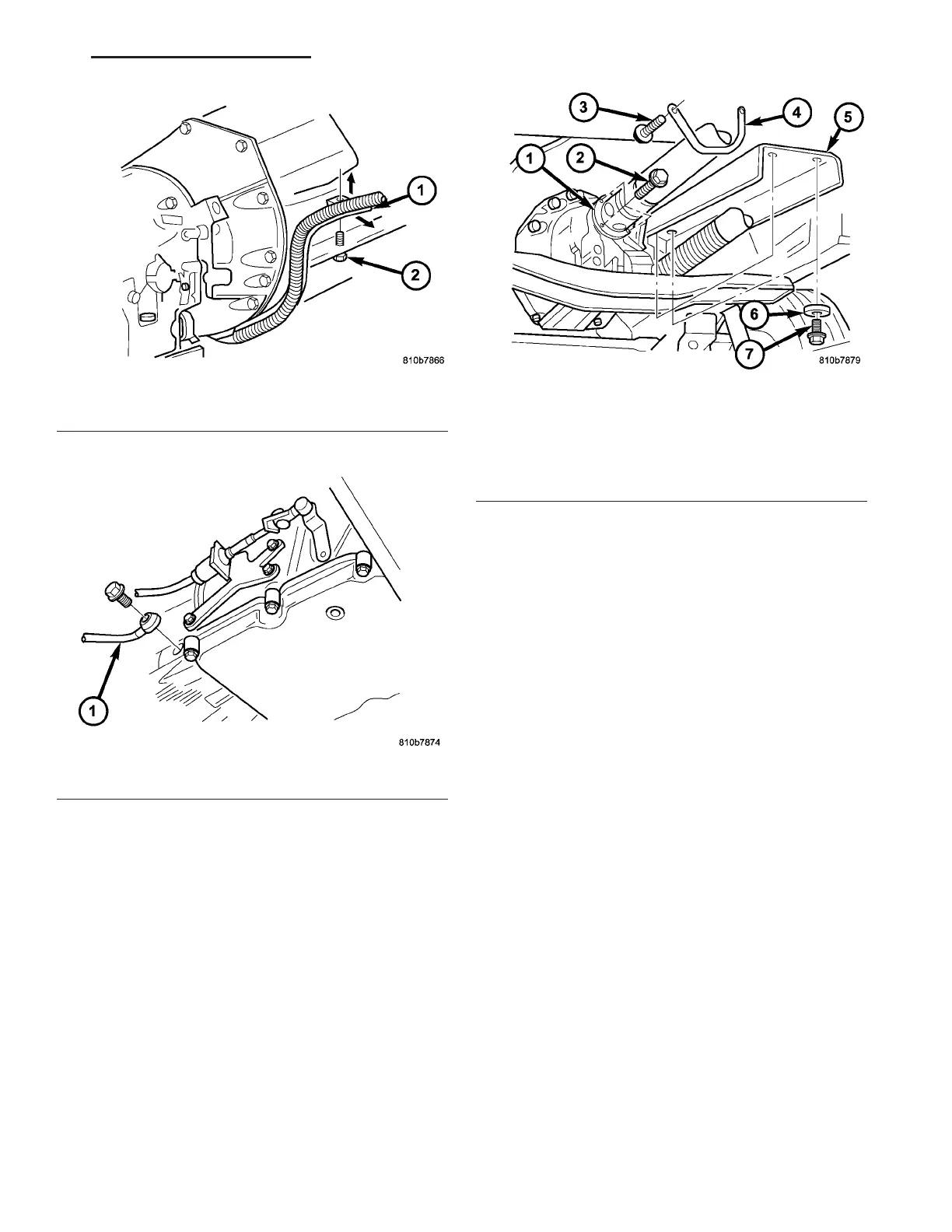
(17) Install exhau st h eat shield (5) (Fig. 76).
(18) Install r etainin g br acket (4) (Fig. 76). Bracket
is asymmet ric. The slanted side mu st be inst alled on
the left side in the direct ion of tr avel.
(19) Atta ch propeller sha ft (1) (Fig. 76) to the
transmission (Refer to 3 - DIF FERE NTIAL & DRIV-
ELINE/PROPELLER SH AFT/PROPELLER SHAFT -
INSTALLATION).
(20) Install oil filler pipe.
(a) Guide oil filler pipe (1) (Fig. 77) down and
into position.
(b) Push lower conn ection of oil filler pipe (1)
(Fig. 77) into th e fill hole in the side of the tr ans-
mission h ousing.
(c) Install bolts (2) (F ig. 77) to cylinder head.
Tighten t he bolts to 8 N·m (71 in.lbs.).
(d) Inst all bolt (3) (Fig. 77) to tran sm ission
flan ge and bolt (2) to t ransm ission h ousing.
Tighten t he bolt to 8 N·m (71 in.lbs.).
Fig. 74 Cable Support
1 - CABLE
2 - BOLT
Fig. 75 Driver’s Side Cooler Line
1 - COOLER LINE
Fig. 76 Propeller Shaft and Heat Shield
1 - PROPELLER SHAFT
2 - BOLT
3 - BOLT
4 - RETAINING BRACKET
5 - HEAT SHIELD
6 - WASHER
7 - BOLT
VA AUTOMATIC TRANSMISSION NAG1 - SERVICE INFORMATION 21 - 63