ASSEMBLY
(1) In st all pist on (6) (Fig. 95) in t he outer m ulti-
ple-disc car rier (8). Check sealing r ing (7), repla ce if
necessar y. The rounded off edges of t he sealing ring
must poin t outwards.
(2) In sert disc spr ing (5). In sert disc sprin g wit h
the cu rva ture towards the piston.
(3) Mount th e Multi-u se Spring Compressor 8900
(9) on th e spring plate an d cla mp until the snap-r ing
groove is exposed.
(4) In sert sna p-r ing (4). Th e collar of t he sna p-r ing
must poin t towards th e multiple-disc pack.
CAUTION: When working with double sided friction
discs, an externally lugged steel plate is installed
first, followed by a friction disc, and continuing on
until all the required discs are installed. When work-
ing with single sided friction discs, an externally
lugged disc is installed first, followed by an inter-
nally lugged disc, and continuing on until all the
required discs are installed. All single sided discs
are installed with the friction side up.
NOTE: Pay attention to the sequence of discs. If the
original clutch discs are reused, be sure to return
the disc identified on disassembly as belonging on
top of the spring plate (3) to its original location.
NOTE: Place new friction multiple-discs in ATF fluid
for one hour before installing.
(5) In st all disk spring (3) and multiple-disc pack
(2) in outer multiple-disc carrier (8).
(6) In sert snap-r ing (1).
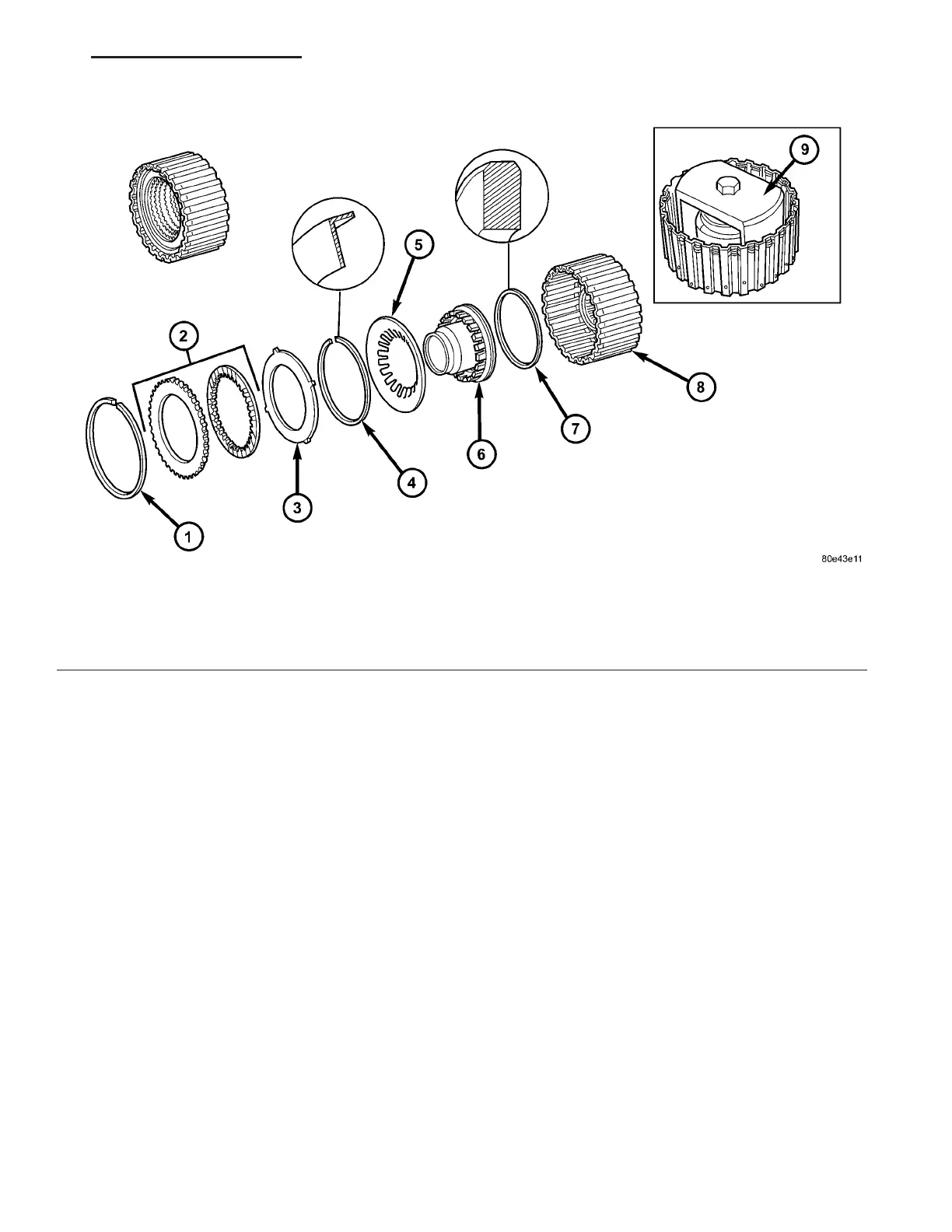
Fig. 95 Input Clutch K3 Components
1 - SNAP-RING 6 - PISTON
2 - MULTIPLE DISC PACK 7 - SEALING RING
3 - DISC SPRING 8 - OUTER DISC CARRIER
4 - SNAP-RING 9 - MULTI-USE SPRING COMPRESSOR 8900
5 - SPRING PLATE
VA AUTOMATIC TRANSMISSION NAG1 - SERVICE INFORMATION 21 - 103