(0.114 in .), 3.2 mm (0.126 in.), an d 3.5 m m (0.138
in.).
ELECT ROH Y DRAU LI C U N I T
DESCRIPTION
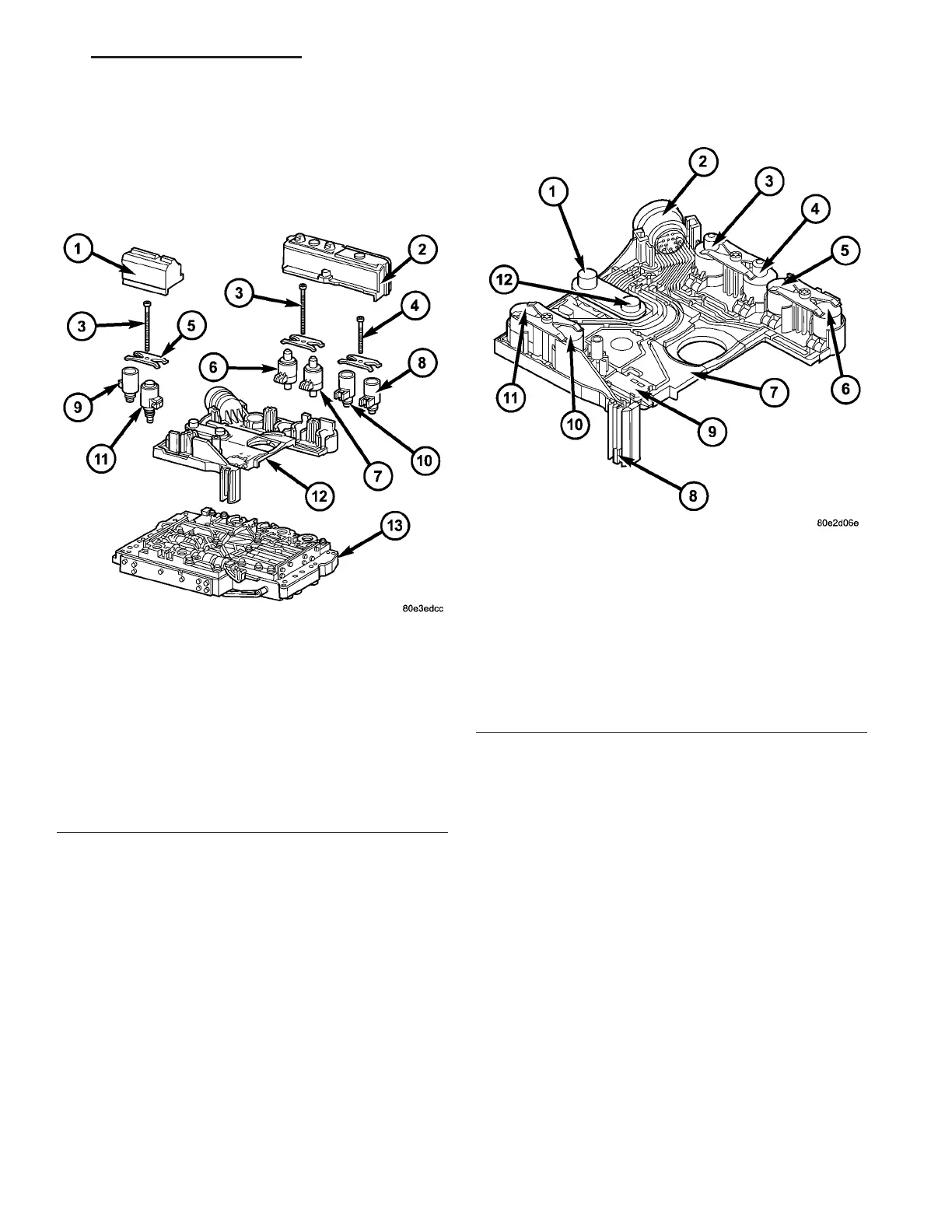
The electrohydraulic contr ol unit (Fig. 99) com -
pr ises the shift plat e (13) made from light a lloy for
the hydr aulic control a nd an electrical control unit
(12). The electr ical control unit (12) comprises of a
su pporting body ma de of pla st ic, into which t he elec-
trical component s (1 - 11) ar e assembled. The su p-
por ting body is mounted on the shift plate (13) and
scr ewed to it.
St rip condu ctors insert ed in to the supporting body
make t he con nection between th e electrical compo-
nent s a nd a plug connector. The con nection to t he
wiring h arness on t he vehicle an d the tr ansmission
control module (TCM) i s produced via this 13-pin
plug connector wit h a bayon et lock.
ELECTRICAL CONTROL UNIT
The electric va lve control unit (7) (Fig. 100) con-
sists of a plastic sh ell which hou ses the RPM sen sor s
(1,12), regulating solenoid valves (3, 4), solenoid
valves (5, 6, 10), t he TCC solenoid va lve (11), the
pa rk/n eutr al contact (9), a nd t he tra nsmission oil
temper ature sensor (8). Conduct or tra cks integra ted
into the shell connect the electric components to a
plug connect ion (2). This 13-pin plug connection (2)
establishes t he conn ection to the vehicle-side ca ble
harness an d to the transm ission con trol m odu le
(TCM). Wit h the exception of the solenoid valves, a ll
other electric componen ts a re fixed to t he conductor
tracks.
HYDRAULIC CONTROL UNIT
Working Pressure (Line Pressure or Operating Pressure)
(p - A)
The wor king pr essu re provides th e pressure su pply
to the hydraulic control and the tra nsmission shift
elem en t s. It is t h e h igh est h ydr a u lic pr ess u r e in t h e
entire hydraulic syst em. Th e workin g pressur e is r eg-
ula ted at the workin g pressure regulating va lve in
Fig. 99 Electrical Unit Components
1 - SOLENOID CAP
2 - SOLENOID CAP
3 - BOLT - M6X32
4 - BOLT - M6X30
5 - LEAF SPRING
6 - MODULATING PRESSURE REGULATING SOLENOID VALVE
7 - SHIFT PRESSURE REGULATING SOLENOID
8 - 3-4 SHIFT SOLENOID
9 - TORQUE CONVERTER LOCK-UP SOLENOID
10 - 1-2/4-5 SHIFT SOLENOID
11 - 2-3 SHIFT SOLENOID
12 - ELECTRICHYDRAULIC CONTROL MODULE
13 - SHIFT PLATE
Fig. 100 Electrical Control Unit
1 - N3 SPEED SENSOR
2 - PLUG CONNECTOR
3 - MODULATING PRESSURE REGULATING SOLENOID
4 - SHIFT PRESSURE REGULATING SOLENOID
5 - 1-2/4-5 SHIFT SOLENOID
6 - 3-4 SHIFT SOLENOID
7 - ELECTRICAL CONTROL UNIT
8 - TRANSMISSION TEMPERATURE SENSOR
9 - STARTER INTERLOCK CONTACT
10 - 2-3 SHIFT SOLENOID
11 - TORQUE CONVERTER LOCK-UP SOLENOID
12 - N2 SPEED SENSOR
VA AUTOMATIC TRANSMISSION NAG1 - SERVICE INFORMATION 21 - 105