(13) Remove the strainers (1, 2) for the modulating
pr essu re a nd shift pr essu re con trol solenoid valves
(Fig. 129) from the valve h ousing.
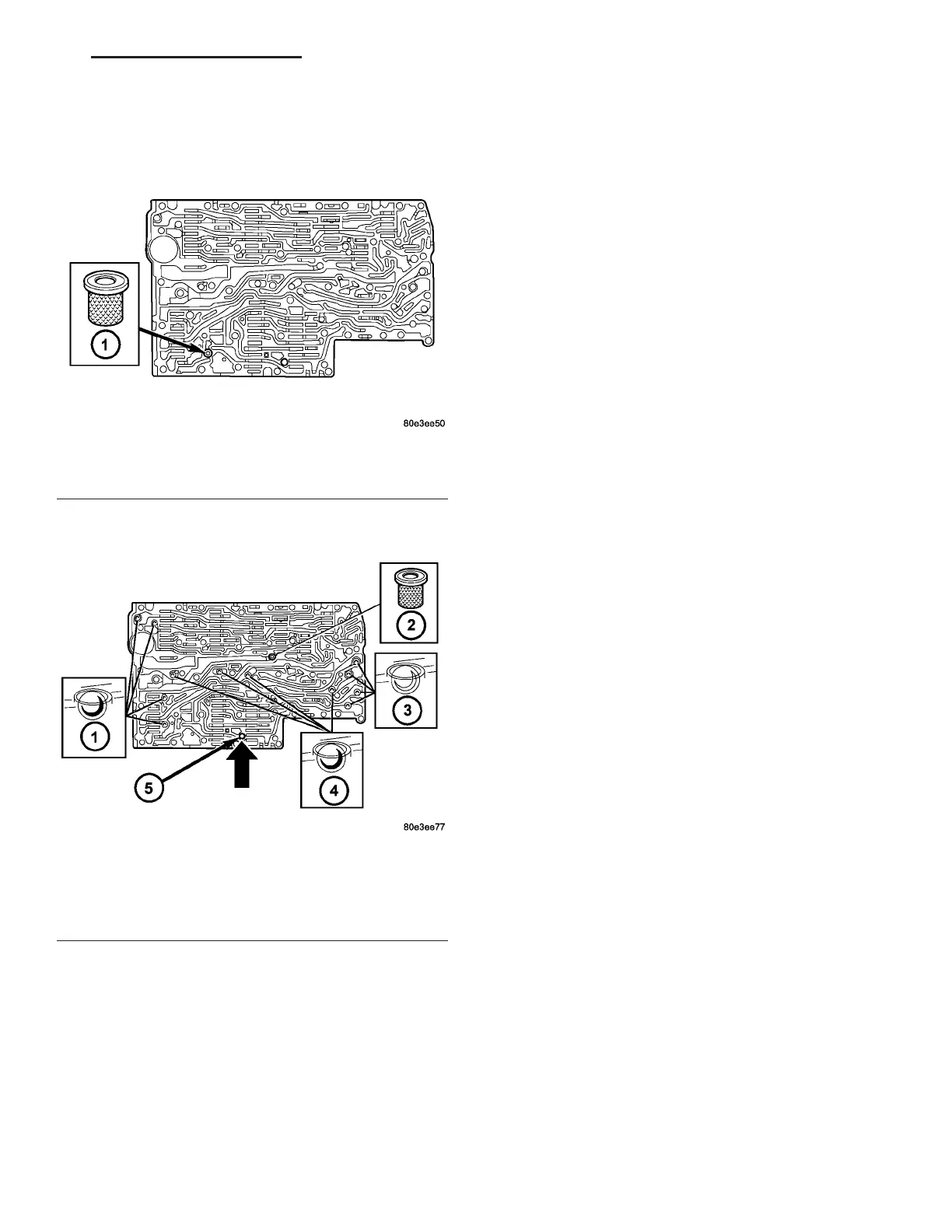
(14) Remove the strainer (1) (Fig. 130) in the inlet
to tor que con vert er lock-up control solenoid valve.
NOTE: A total of 12 valve balls are located in the
valve body, four made from plastic (4) and eight
from steel (1, 3).
(15) Not e the location of all check balls (1, 3, 4)
(Fig. 131) and the cen tral st rainer (2) for r e-installa -
tion. Remove a ll check balls (1, 3, 4) and th e centr al
st rainer (2).
Fig. 130 Converter Lock-up Solenoid Valve Strainer
Location
1 - CONVERTER LOCK-UP SOLENOID STRAINER
Fig. 131 Check Balls and Strainer Location
1 - STEEL CHECK BALLS
2 - CENTRAL STRAINER
3 - STEEL CHECK BALLS
4 - PLASTIC CHECK BALLS
5 - PLAIN DOWEL PIN
VA AUTOMATIC TRANSMISSION NAG1 - SERVICE INFORMATION 21 - 123