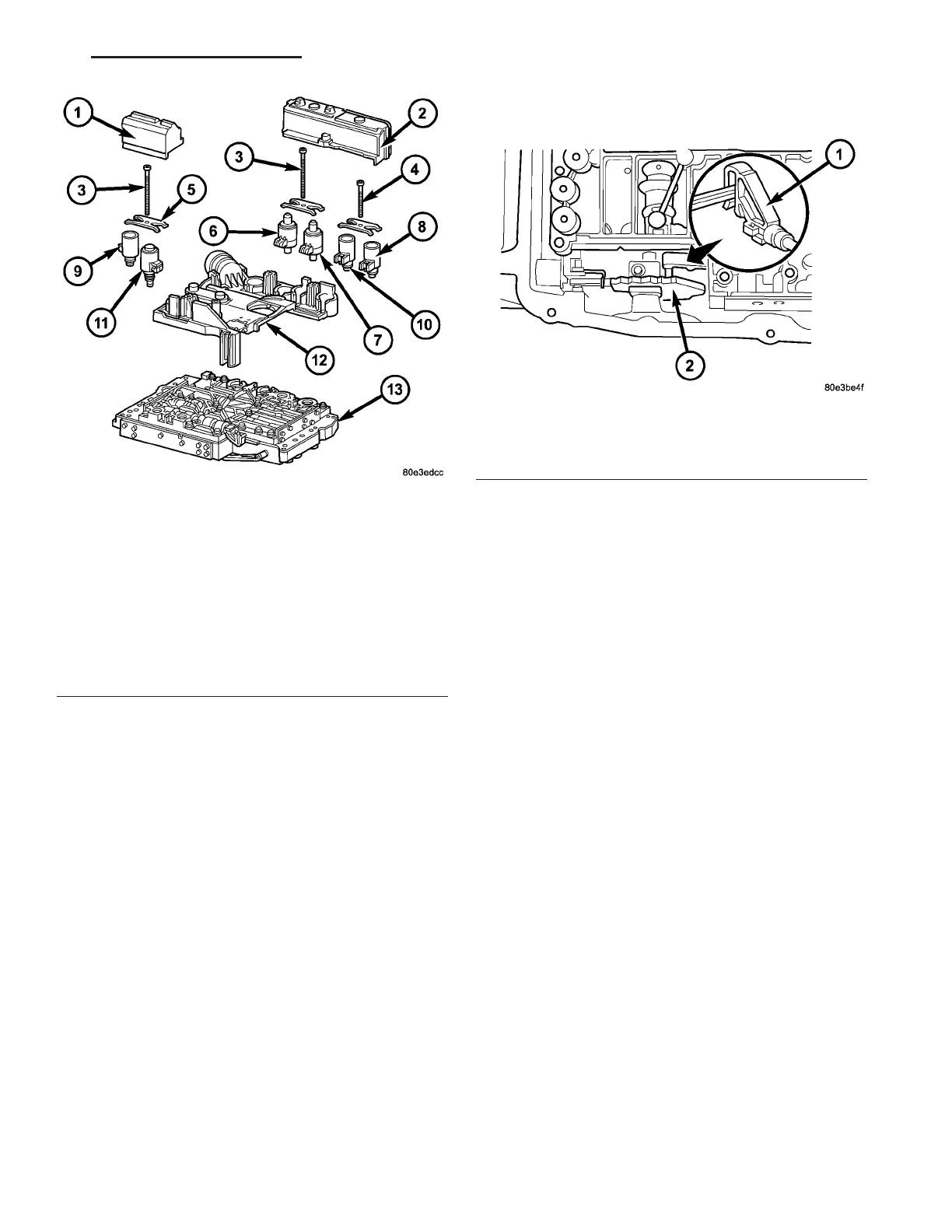
(13) Install th e electr ohydraulic con trol m odu le
(12) ont o the shift plate (13) (Fig. 142).
(14) Bend the r etaining lug on st iffening rib on
transmission oil tem perat ure sensor to ret ain the
electrohydr aulic control m odu le.
(15) Install t he solenoid valves (6 - 11) int o shift
plate (13).
NOTE: Check O-rings on solenoid valves for dam-
age and replace if necessary.
(16) Install the lea f sprin gs (5).
(17) Install t he Torx! socket bolts (3, 4) (Fig. 142).
Tighten t he bolts to 8 N·m (71 in.lbs.).
NOTE: Pay attention to the different lengths of the
Torx" socket bolts.
(18) Install the solen oid caps (1, 2).
(19) Install the electr ohydraulic u nit into th e vehi-
cle.
INSTALLATION
(1) Position th e electroh ydrau lic unit in the tr ans-
mission h ousing.
(2) In sert selector valve (1) (Fig. 143) in driver of
detent plate (2). When insta lling the electrohydr aulic
control m odu le in t he tr ansmission hou sing, t he plas-
tic part of the selector valve (1) mu st enga ge in the
dr iver of the det ent pla te (2).
Fig. 142 Electrical Unit Components
1 - SOLENOID CAP
2 - SOLENOID CAP
3 - BOLT - M6X32
4 - BOLT - M6X30
5 - LEAF SPRING
6 - MODULATING PRESSURE REGULATING SOLENOID VALVE
7 - SHIFT PRESSURE REGULATING SOLENOID
8 - 3-4 SHIFT SOLENOID
9 - TORQUE CONVERTER LOCK-UP SOLENOID
10 - 1-2/4-5 SHIFT SOLENOID
11 - 2-3 SHIFT SOLENOID
12 - ELECTRICHYDRAULIC CONTROL MODULE
13 - SHIFT PLATE
Fig. 143 Connect The Selector Valve To The Detent
Plate
1 - SELECTOR VALVE
2 - DETENT PLATE
VA AUTOMATIC TRANSMISSION NAG1 - SERVICE INFORMATION 21 - 129