Engine st arts must not be possible in an y oth er gear
position .
(3) With floor shift lever handle push-button not
depressed and lever in:
(a) PARK position - Apply forwa rd force on cen-
ter of ha ndle and remove pressu re. Engine starts
must be possible.
(b) PARK position - Apply rear ward force on cen -
ter of ha ndle and remove pressu re. Engine starts
must be possible.
(c) NEUTRAL position - Nor mal position . Engine
st arts must be possible.
(d) NEUTRAL position - En gine runnin g and
brakes applied, apply forwa rd for ce on center of
sh ift ha ndle. Tra nsmission shall not be able to shift
from NE UTRAL to RE VERSE.
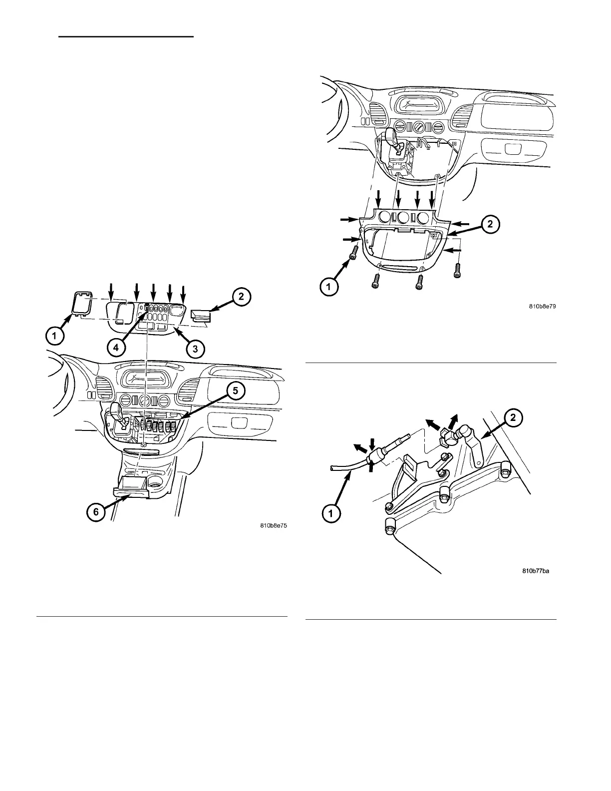
REMOVAL
(1) Move selector lever t o position “D”.
(2) Remove top (3) (Fig. 159) of t he center section
of inst rumen t pa nel.
(3) Remove bottom (2) (Fig. 160) of the cen ter sec-
tion of instr umen t panel.
(4) Pry ba ll socket of transmission shift ca ble off
ball knob a t t he shift lever assembly (SLA). Use a
su itable slot ted screwdr iver.
(5) Raise and support vehicle.
(6) Detach shift cable (1) a t transmission .
(a) Un latch ba ll socket la tch (Fig. 161) of cable.
(b) Unclip shift cable retainer from reta iner
bracket. Wh en pullin g out cable, pr ess together
hooks of shift cable retainer at the points sh own
(arrows).
Fig. 159 Remove Top Section Of Center Instrument
Panel
1 - SHIFT LEVER ASSEMBLY FRAME TRIM
2 - STORAGE COMPARTMENT
3 - TOP CENTER PART OF INSTRUMENT PANEL
4 - SCREW
5 - PLUG CONNECTIONS
6 - ASHTRAY
Fig. 160 Remove Bottom Section Of Center
Instrument Panel
1 - SCREW
2 - BOTTOM CENTER PART OF INSTRUMENT PANEL
Fig. 161 Remove Shift Cable From Transmission
1 - SHIFT CABLE
2 - TRANSMISSION SHIFT LEVER
VA AUTOMATIC TRANSMISSION NAG1 - SERVICE INFORMATION 21 - 139