INSTALLATION
CAUTION: Verify that the geartrain end-play shim is
properly installed over the output shaft and against
the park gear.
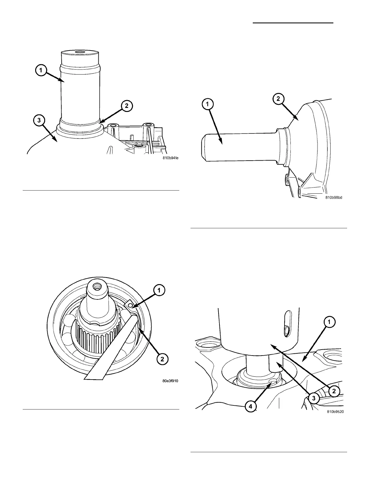
(1) In st all output sh aft bearing in the rear tra ns-
mission housing. Using Bearing Insta ller 9287 (1)
(Fig. 195), install t he output shaft bearing (2) into
the tr ansmission housing. The c lo s e d s i d e o f t h e
plastic cage must point towards the parking
lock ge ar.
(2) In st all the r etainin g ring (1) (F ig. 196). En sure
that th e ret ain ing ring is sea ted correct ly in the
groove.
(3) Check that t here is no play between the bear-
ing and the ret ain ing rin g using feeler gauge.
(4) There must be no play bet ween the ret ain ing
ring and the bea ring. If th e ring can not be installed,
athinnerringmustbeused.Ifthereisplaybetween
the ring a nd t he bear ing, a thicker ring must be
insta lled. Ret ain ing rings are available in thick-
nesses of 2.0 mm (0.079 in.), 2.1 mm (0.083 in.), an d
2.2 mm (0.087 in.).
(5) In st all the output sh aft wa sh er onto the output
sh aft.
(6) In st all a new transmission rea r seal int o the
transmission ca se with Seal Insta ller 8902A (1) (Fig.
197).
(7) Verify that the tr ansmission is in PARK in
order to prepa re for t he installation of the output
sh aft nut .
(8) In st all the propeller sh aft fla nge onto the out-
pu t sha ft an d install an new flange nut. Tigh ten the
flan ge nu t to 200 N·m (147.5 ft.lbs.).
Fig. 195 Install Output Shaft Bearing
1 - BEARING INSTALLER 9287
2 - BEARING
3 - TRANSMISSION CASE
Fig. 196 Install Rear Output Shaft Retaining Ring
1 - RETAINING RING
2 - OUTPUT SHAFT BEARING
Fig. 197 Install Output Shaft Seal
1 - SEAL INSTALLER 8902A
2 - TRANSMISSION CASE
Fig. 198 Align Staking Tool 9078
1 - PROPELLER SHAFT FLANGE
2 - STAKING TOOL 9078
3 - ALIGNMENT PIN
4 - OUTPUT SHAFT NOTCH
21 - 158 AUTOMATIC TRANSMISSION NAG1 - SERVICE INFORMATION VA