(9) St ake th e output sha ft nut to the outpu t shaft
as follows.Place the Sta kin g Tool 9078 (2) a nd Dr iver
Handle C-4171 onto the ou tput sha ft.
(10) Rotate the Staking Tool 9078 (2) un til the
alignm ent pin (3) engages th e outpu t sh aft notch (4)
(Fig. 198).
(11) Press downwa rd on the sta king tool (1) until
the staking pin (3) cont acts t he output sha ft nu t
flan ge (2) (F ig. 199).
(12) Strike th e Driver handle C-4171 with a suit-
able h ammer u ntil the output shaft nut is secu rely
st aked to the output sha ft.
(13) Install th e pr opeller sha ft (Refer to3-DIF-
FERE NTIAL & DRIVELINE/P ROPELLER SH AFT/
PROPELLER SH AFT - INSTALLATION).
OU T PU T SH AFT SEAL
REMOVAL
(1) Remove t he pr opeller sha ft (Refer to3-DIF-
FERE NTIAL & DRIVELINE/P ROPELLER SH AFT/
PROPELLER SH AFT - REMOVAL). Move pr opeller
sh aft to t he right and tie up.
(2) Verify that the tr ansmission is in PARK in
order to prepa re for the removal of the output shaft
nut.
(3) Remove the nut holding th e pr opeller shaft
flan ge to the ou tput shaft and rem ove the fla nge.
(4) Remove th e out pu t shaft seal with suitable
scr ew an d slide hammer.
INSTALLATION
(1) Position the new output shaft seal over t he out -
pu t shaft and a gainst the transmission case.
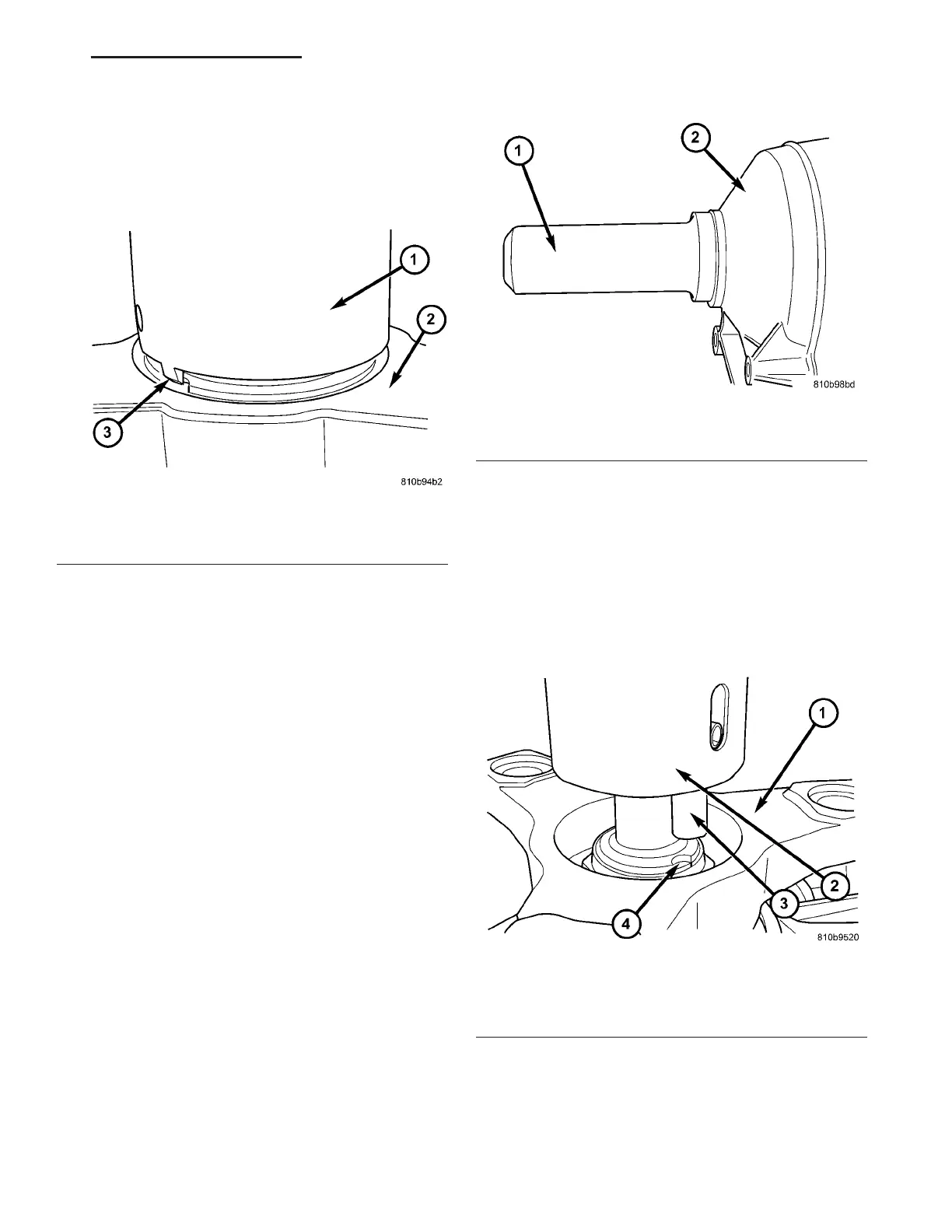
(2) Use Sea l Installer 8902A (1) (Fig. 200) to
ins tall the s e al.
(3) Verify that the tr ansmission is in PARK in
order to prepa re for t he installation of the output
sh aft nut .
(4) In st all the propeller sh aft fla nge onto the out-
pu t sha ft an d install an new flange nut. Tigh ten the
flan ge nu t to 200 N·m (147.5 ft.lbs.).
(5) St ake th e output sha ft nut to the outpu t shaft
as follows.Place the Sta kin g Tool 9078 (2) a nd Dr iver
Handle C-4171 onto the ou tput sha ft.
(6) Rotat e the Staking Tool 9078 (2) until th e
alignm ent pin (3) engages th e outpu t sh aft notch (4)
(Fig. 201).
Fig. 199 Stake Output Shaft Nut
1 - STAKING TOOL 9078
2 - PROPELLER FLANGE
3 - STAKING PIN
Fig. 200 Install the Output Shaft Seal
1 - SEAL INSTALLER 8902A
2 - TRANSMISSION CASE
Fig. 201 Align Staking Tool 9078
1 - PROPELLER SHAFT FLANGE
2 - STAKING TOOL 9078
3 - ALIGNMENT PIN
4 - OUTPUT SHAFT NOTCH
VA AUTOMATIC TRANSMISSION NAG1 - SERVICE INFORMATION 21 - 159