(7) Press downwa rd on the staking tool u ntil the
st aking pin (3) conta cts the output sha ft nut flange
(2) (Fig. 202).
(8) St rike t he Dr iver han dle C-4171 with a su it-
able h ammer u ntil the output shaft nut is secu rely
st aked to the output sha ft.
(9) In st all the propeller shaft (Refer to3-DIF-
FERE NTIAL & DRIVELINE/P ROPELLER SH AFT/
PROPELLER SH AFT - INSTALLATION).
PARK LOCK CABLE
REMOVAL
(1) Disconn ect batt ery.
(2) Move selector lever t o position “D”.
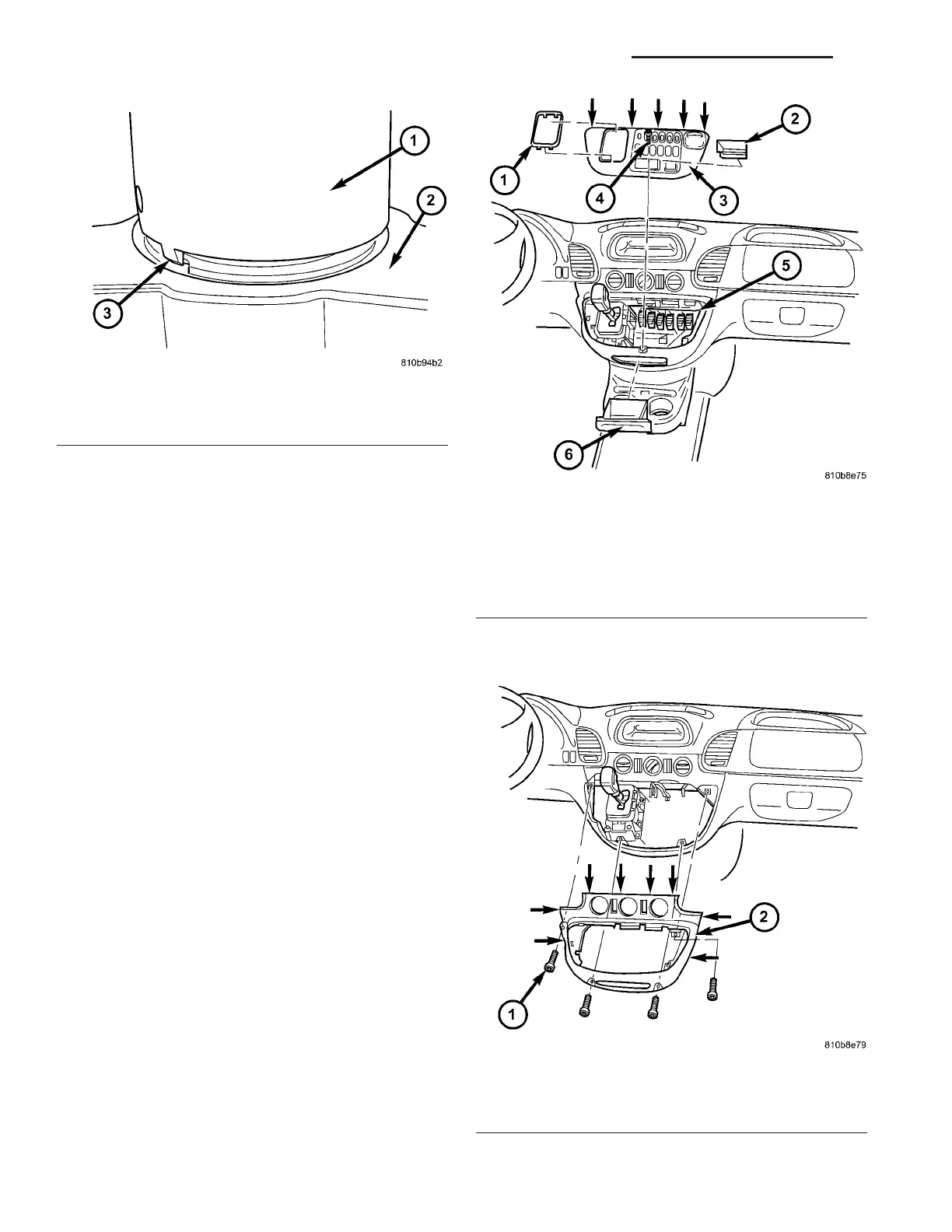
(3) Remove top section (3) (Fig. 203) of the center
section of instr umen t pa nel.
(4) Remove bot tom sect ion (2) (F ig. 204) of t he cen-
ter section of in st rument panel.
Fig. 202 Stake Output Shaft Nut
1 - STAKING TOOL 9078
2 - PROPELLER FLANGE
3 - STAKING PIN
Fig. 203 Remove Top Section Of Center Instrument
Panel
1 - SHIFT LEVER ASSEMBLY FRAME TRIM
2 - STORAGE COMPARTMENT
3 - TOP CENTER PART OF INSTRUMENT PANEL
4 - SCREW
5 - PLUG CONNECTIONS
6 - ASHTRAY
Fig. 204 Remove Bottom Section Of Center
Instrument Panel
1 - SCREW
2 - BOTTOM CENTER PART OF INSTRUMENT PANEL
21 - 160 AUTOMATIC TRANSMISSION NAG1 - SERVICE INFORMATION VA