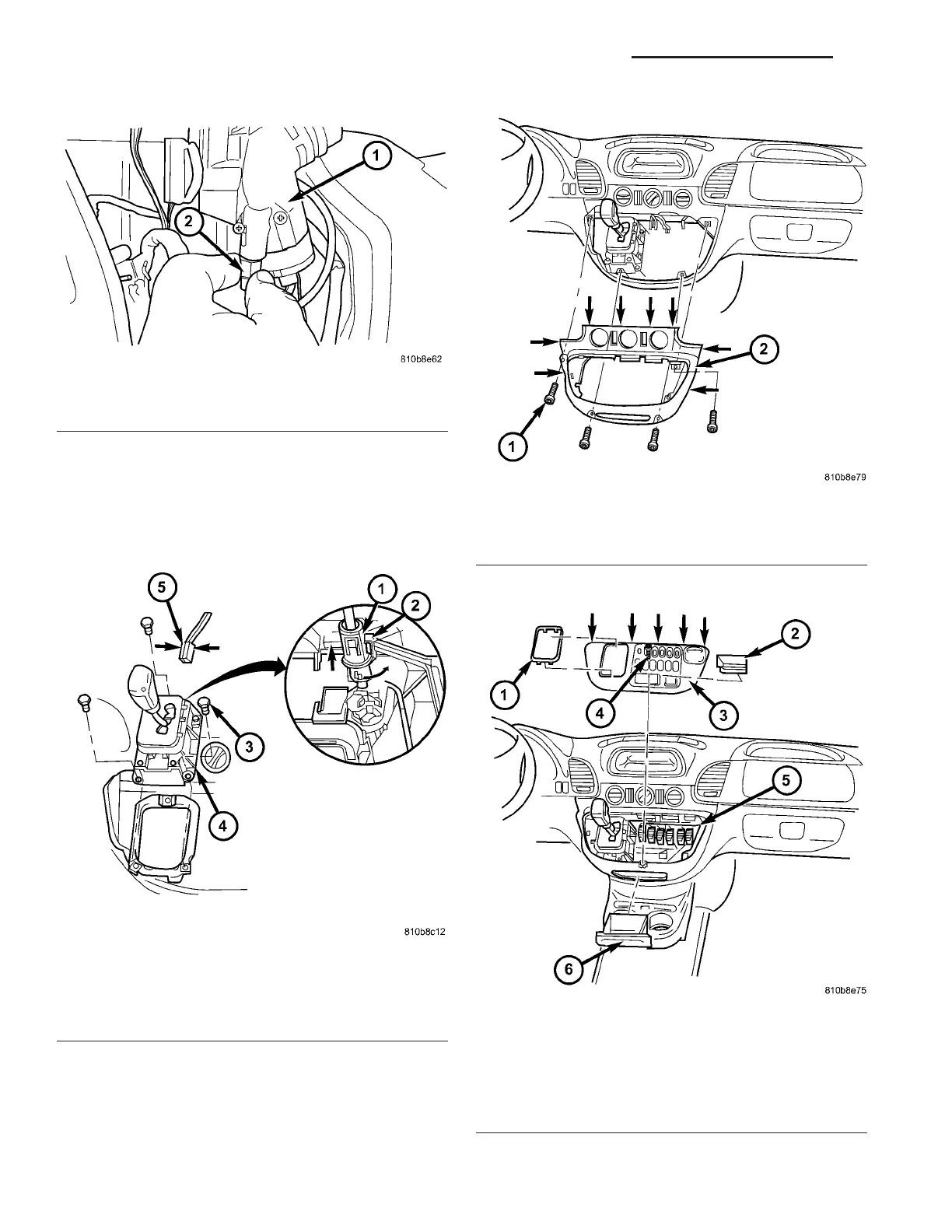
(5) Connect t he pa rk lock cable coupling (1) (Fig.
210) to the shift lever assembly (SLA). P ress locking
tab (2) toget her and push coupling (1) a gainst th e
spring force int o the SLA, twist through 90° (right or
left) until locked.
(6) In st all the bot tom section (2) (Fig. 21 1) of t he
center section of instr umen t pa nel.
(7) In st all th e top section (3) (Fig. 212) of the cen-
ter section of in st rument panel.
(8) Connect batt ery.
Fig. 209 Tighten Park Lock Cable to Ignition Switch
1 - IGNITION SWITCH
2 - PARK LOCK CABLE
Fig. 210 Engage Park Lock Cable to SLA
1 - PARK LOCK CABLE COUPLING
2 - LOCK TAB
3 - BOLT
4 - SHIFT LEVER ASSEMBLY (SLA)
5 - CONNECTOR
Fig. 211 Install Bottom Section Of Center Instrument
Panel
1 - SCREW
2 - BOTTOM CENTER PART OF INSTRUMENT PANEL
Fig. 212 Install Top Section Of Center Instrument
Panel
1 - SHIFT LEVER ASSEMBLY FRAME TRIM
2 - STORAGE COMPARTMENT
3 - TOP CENTER PART OF INSTRUMENT PANEL
4 - SCREW
5 - PLUG CONNECTIONS
6 - ASHTRAY
21 - 162 AUTOMATIC TRANSMISSION NAG1 - SERVICE INFORMATION VA