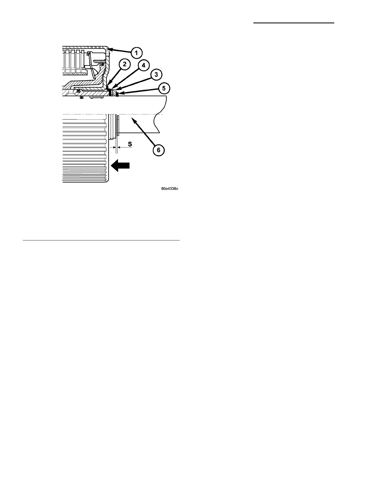
NOTE: During the test, apply a contact force by
hand to K3 in the direction of the arrow.
(8) In spect axial play (Fig. 221) between shim (10)
and retaining ring (11). Ch eck a xia l pla y “S” between
sh im (10) and r etaining rin g (1) u sing a feeler gau ge.
Clearance should be 0.15-0.6 mm (0.006-0.024 in.).
Sh ims are available in thicknesses of 3.0 mm (0.118
in.), 3.4 m m (0.134 in.), and 3.7 mm (0.146 in.).
Adjust as n ecessa ry
SH I FT M ECH AN I SM
DESCRIPTION
The au tomat ic transmission is oper ated with the
help of a shift lever assembly (SLA) loca ted in the
center console. Th ere are four positions to which the
selection lever can be shifted: P, R, N, D. In addition ,
the selector lever can be moved sidewa ys (+/-) in posi-
tion “D” to adjust th e shift range.
All selector lever positions, as well as selected shift
ranges in position “D”, are identified by th e SLA. The
information is t hen sent to the tr ansmission contr ol
module (TCM) via a ha rdwir e connect ion. At t he
sa me time, the selector lever positions “P”, “R”, “N”
and “D” a re transmitted by a sh ift cable to th e selec-
tor shaft in the tra nsmission.
The SLA is comprised of the following functions:
• Key l ock: Dependin g on the select or lever posi-
tion, the ignition lock is locked/u nlocked, i.e., th e
ign ition key ca n be removed on ly if the selector lever
is in position “P”. A park lock cable is u sed to per-
form this function.
• Park lock: The select or lever is not relea sed
from postion “P” until t he bra ke pedal ha s been
applied and t he ignition key is in dr iving position.
Sh ift lock is controlled by the brake light switch in
conjunction with a locking solenoid in the SLA. As
soon a s the brake pedal is applied firmly, th e locking
solenoid is r etra cted to un lock the select or lever. If
the selector lever can not be m oved out of posit ion “P”
du e to a ma lfun ction, the shift lock function can be
overr iden (see operator’s ma nua l).
• Reverse inhibitor: As soon as th e veh icle
speed exceeds a pprox. 4 m ph , it is n o longer possible
to move the selector lever fr om position “N” to posi-
tion “R”.
OPERATION
With t he selector lever in position “D”, t he trans-
mission control module (TCM) a utomatica lly sh ifts
the gear s t hat ar e best-suited to th e current operat-
ing sit uation. This m eans th at shifting of gear s is
continuou sly adjusted t o current dr iving and operat -
ing condit ions in line with the selected shift range
and the accelera tor pedal position . Starting off is
alwa ys perfor med in 1st gear.
The selector lever posit ions are det ermined by th e
slider position of a pot entiomet er in th e shift lever
assembly (SLA). The sh ift pattern diagram (position
display) and the program select or a re illuminated by
the LEDs.
The cur rent selector lever position or, if t he shift
range has been limited, the curren t shift r ange is
indicated in the LCD display in the in st rument clus-
ter.
The permissible shifter positions a nd t ransmission
operat ing ran ges ar e:
• P = Par king lock an d engine st arting.
• R=Reverse.
• N = Neu tral a nd engine star ting (n o power is
transmit ted to t he axles).
• D = Th e shift r ange includes all for ward gear s.
• 4= Shift ran ge is lim ited t o gea rs 1 to 4.
• 3= Shift ran ge is lim ited t o gea rs 1 to 3.
• 2= Shift ran ge is lim ited t o gea rs 1 to 2.
• 1= Shift ran ge is lim ited t o the 1st gear.
The shift range can be adju st ed to the curren t
operat ing condition s by tippin g the selector lever to
the left-h and side (“-”) or t he right -han d side (“+”)
when in position “D”. If the shift range is limited, t he
display in th e in st rumen t clu st er indica tes th e
selected shift r ange and not t he curr ently engaged
gear.
Tipping th e shift lever will have th e following
results:
Fig. 221 Check Center and Rear Planetary End-Play
1 - DRIVING CLUTCH K3
2 - THRUST WASHER
3 - SHIM
4 - AXIAL NEEDLE BEARING
5 - RETAINING RING
6 - OUTPUT SHAFT WITH CENTER PLANETARY CARRIER
21 - 168 AUTOMATIC TRANSMISSION NAG1 - SERVICE INFORMATION VA