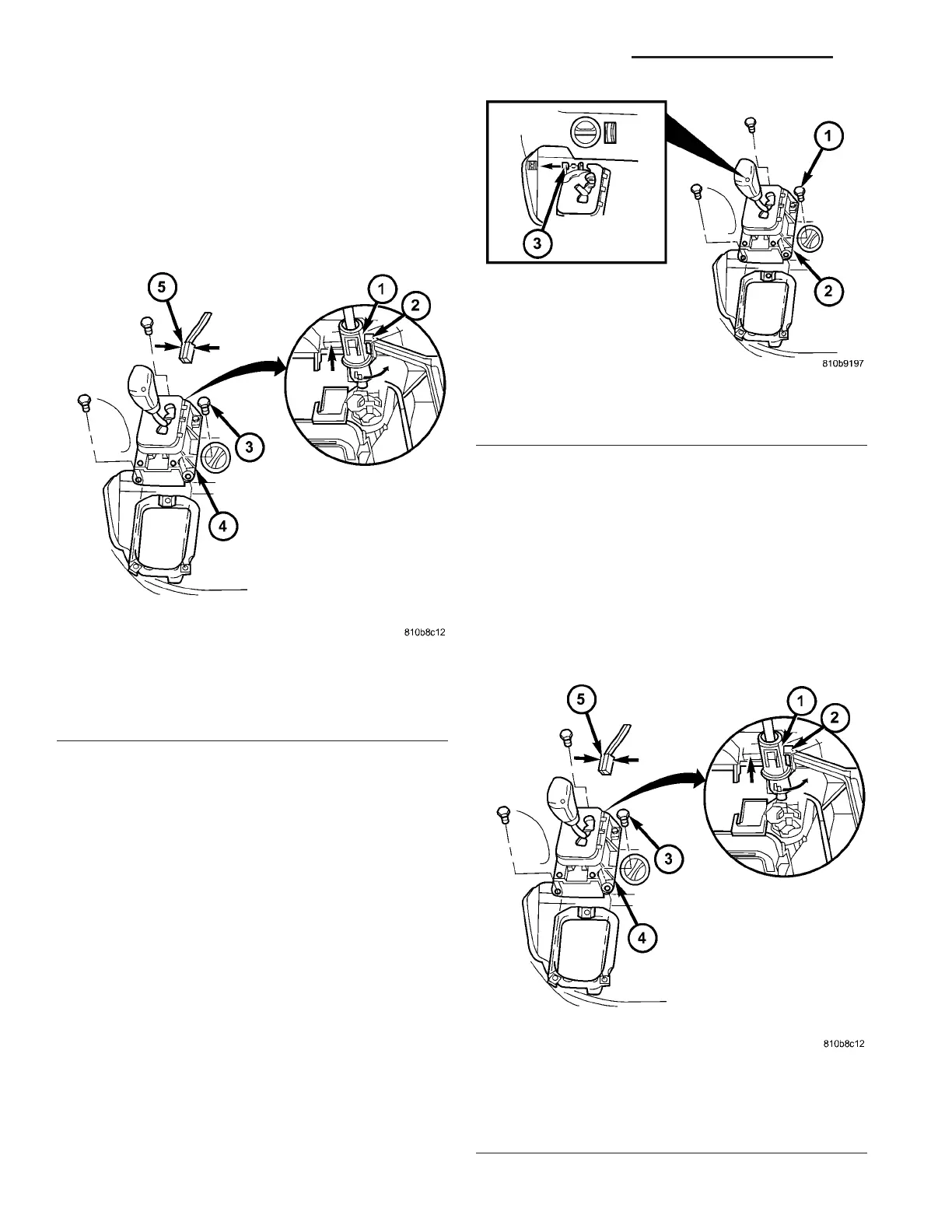
(4) Disconn ect the park lock cable coupling (1)
(Fig. 224) from the shift lever assembly (SLA). P ress
locking ta b (2) toget her a nd push coupling (1) against
the spring force into th e SLA, twist th rough 90°
(right or left ) and pull off.
(5) Disconn ect connect or plug (5) from SLA. When
disconnectin g plug, pr ess toget her at points shown
(arrows).
(6) Pry ball socket (4) of tra nsmission shift cable
off ball kn ob a t the SLA. Use a suitable slotted
scr ewdriver.
(7) Unscr ew bolt s (1) (Fig. 225).
(8) Move selector lever t o position “P”.
(9) Remove the SLA (2) from th e veh icle.
INSTALLATION
(1) Position the sh ift lever assembly (SLA) onto
the vehicle.
(2) In st all t he bolts to hold th e SLA t o the vehicle.
Tighten t he bolts to 6 N·m (53 in.lbs.).
(3) Connect t he pa rk lock cable coupling (1) (Fig.
226) to the SLA. Press locking tab (2) togeth er and
pu sh coupling (1) again st the sprin g force into th e
SLA, twist throu gh 90° (r igh t or left) u ntil locked.
(4) Connect the con nector plug (5) to t he SLA.
Fig. 224 Disengage Park Lock Cable From SLA
1 - PARK LOCK CABLE COUPLING
2 - LOCK TAB
3 - BOLT
4 - SHIFT LEVER ASSEMBLY (SLA)
5 - CONNECTOR
Fig. 225 Remove SLA
1 - BOLT
2 - SLA
3 - SHIFT CABLE
Fig. 226 Engage Park Lock Cable to SLA
1 - PARK LOCK CABLE COUPLING
2 - LOCK TAB
3 - BOLT
4 - SHIFT LEVER ASSEMBLY (SLA)
5 - CONNECTOR
21 - 170 AUTOMATIC TRANSMISSION NAG1 - SERVICE INFORMATION VA