(5) Turn on ignition an d a pply brakes. Move selec-
tor lever back to posit ion “D”.
(6) In st all t he tran sm ission shift cable onto the
ball knob at the SLA.
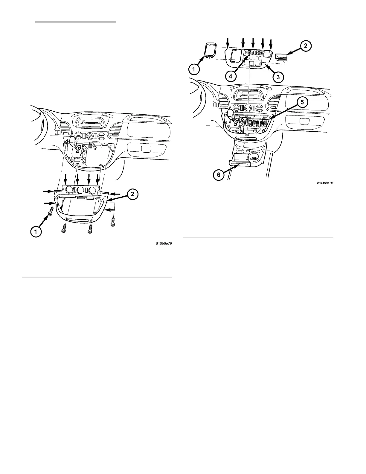
(7) In st all the bottom (2) (Fig. 227) of the center
section of instr umen t pa nel.
(8) In st all the t op (3) (F ig. 228) of the center sec-
tion of instr umen t panel.
(9) Verify repa ir.
SOLEN OI D
DESCRIPTION
The typical electrical solenoid u sed in aut omotive
applica tion s is a linea r a ctuat or. It is a device tha t
pr odu ces motion in a stra igh t line. This straight line
motion can be eit her forwar d or backward in direc-
tion, and shor t or long distance.
A solenoid is an electrom echan ical device that uses
a magnetic force to per form work. It consist s of a coil
of wire, wrapped a round a ma gnet ic cor e ma de from
st eel or ir on, and a sprin g loaded, movable plun ger,
which per forms th e work, or straight line m otion.
The solenoids used i n tran sm ission applications
are att ached t o valves which can be classified as nor-
mally open or normally closed.Thenormally
open solen oid valve is defined as a valve which
allows hydraulic flow when no cu rren t or voltage is
applied to the solenoid. Th e normally closed sole-
noid valve is defin ed as a va lve which does not a llow
hydra ulic flow when no cu rren t or volt age is applied
to th e solen oid. Th ese va lves perform hydraulic con-
trol functions for the t ran smission a nd must there-
fore be durable a nd tolerant of dir t par ticles. For
these reason s, the valves have h ardened st eel pop-
pets an d ball va lves. The solenoids operate th e va lves
Fig. 227 Install Bottom Section Of Center
Instrument Panel
1 - SCREW
2 - BOTTOM CENTER PART OF INSTRUMENT PANEL
Fig. 228 Install Top Section Of Center Instrument
Panel
1 - SHIFT LEVER ASSEMBLY FRAME TRIM
2 - STORAGE COMPARTMENT
3 - TOP CENTER PART OF INSTRUMENT PANEL
4 - SCREW
5 - PLUG CONNECTIONS
6 - ASHTRAY
VA AUTOMATIC TRANSMISSION NAG1 - SERVICE INFORMATION 21 - 171