direct ly, which mean s th at the solenoids must ha ve
very high outputs to close the valves a gainst th e siz-
able flow area s and line pressures found in cur rent
transmission s. Fast respon se tim e is a lso necessary
to ensure accu rate contr ol of the transmission.
The str ength of t he ma gnet ic field is the primary
force tha t det ermines the speed of opera tion in a par-
ticular solenoid design. A stron ger magnetic field will
cause the plunger to move at a grea ter speed th an a
weaker one. There are basically two wa ys to increa se
the for ce of th e magnet ic field:
1. In crease the amount of cur rent applied to the
coil or
2. In crease the n umber of turns of wir e in the coil.
The most common pract ice is to increase the nu m-
ber of tur ns by u sing thin wire that can completely
fill t he available space within t he solenoid hou sing.
The str engt h of the spring and th e length of t he
plunger also contribut e to th e response speed possi-
ble by a particular solenoid design.
A solenoid ca n also be described by the met hod by
which it is controlled. Som e of the possibilities
include variable force, pu lse-widt h modulated, con-
st ant ON, or du ty cycle. Th e variable force and pu lse-
width modulated versions utilize similar methods to
control the cu rren t flow th rough the solenoid t o posi-
tion th e solenoid plunger at a desired posit ion some-
where between fu ll ON and full OF F. The constant
ON an d duty cycled versions con trol the voltage
across the solenoid to allow eith er fu ll flow or no flow
through th e solenoid’s valve.
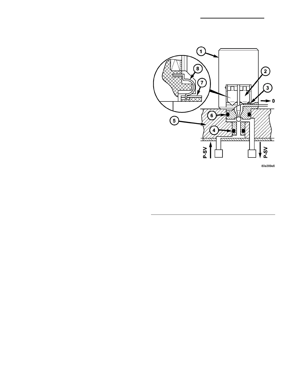
UPSHIFT / DOWNSHIFT SOLENOID VALVES
The solenoid valves (1) for upshifts an d downshifts
(Fig. 229) ar e located in the shell of th e electr ic con-
trol unit an d pr essed against th e shift plat e with a
sprin g.
The solen oid valves (1) initiate the upshift and
downshift pr ocedu res in t he shift plat e.
The solenoid va lves (1) are sealed off from th e
valve housing of the shift plate (5) by two O-rings (4,
6). The con tact springs (8) at the solenoid valve
enga ge in a slot in the conductor t racks (7). The force
of the conta ct spring (8) ensu res safe con tacts.
Fig. 229 Upshift/Downshift Solenoid Valves
1 - UPSHIFT/DOWNSHIFT SOLENOID VALVE
2 - CONTACT SPRING
3 - CONDUCTOR TRACK
4 - O-RING
5 - VALVE HOUSING OF SHIFT PLATE
6 - O-RING
7 - CONDUCTOR TRACK
8 - CONTACT SPRING
21 - 172 AUTOMATIC TRANSMISSION NAG1 - SERVICE INFORMATION VA