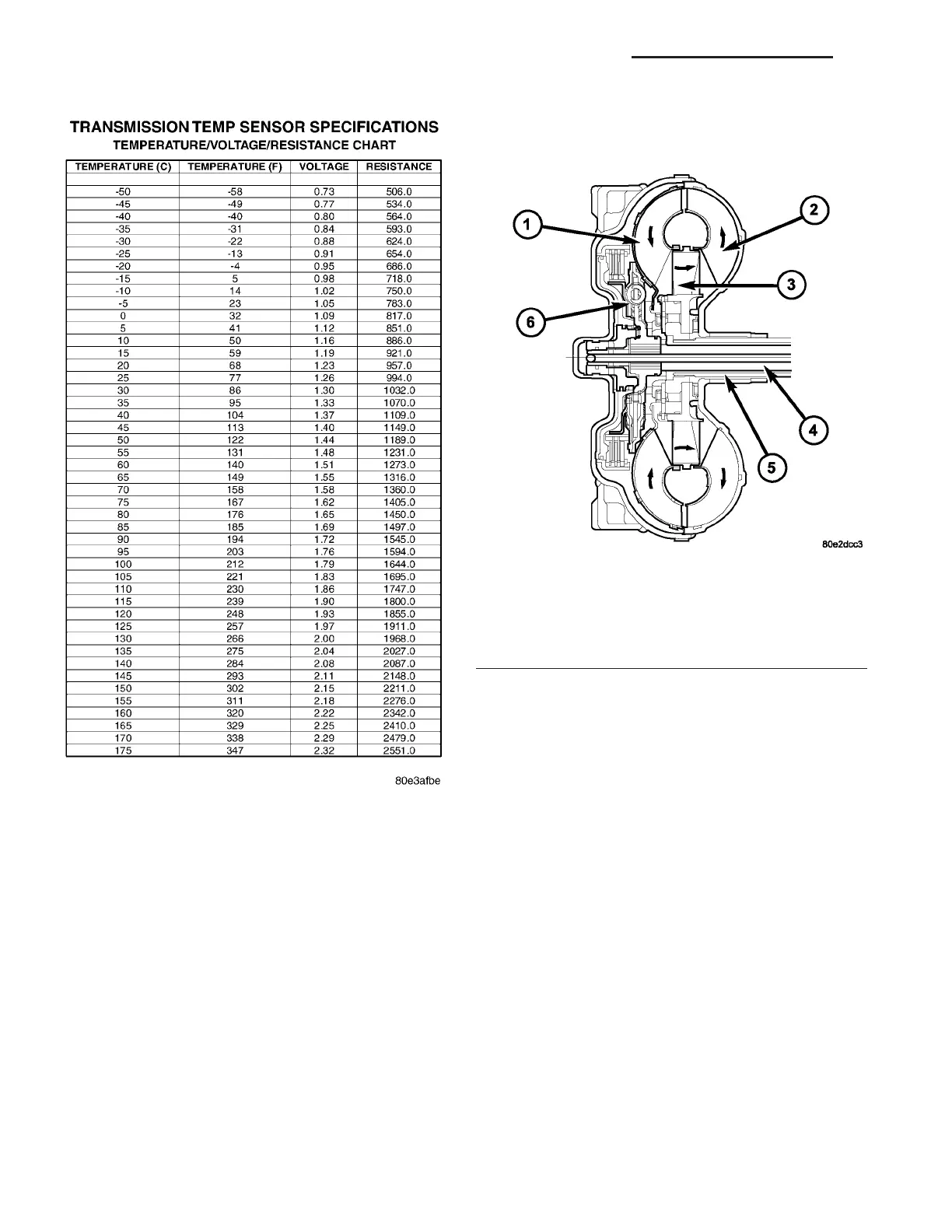
Refer to t he Transmission Temperatur e Sensor
Specifica tions t able (Fig. 241) for the rela tionship
between tran sm ission temper atur e, sensor voltage,
and sensor resistance.
TORQUE CONVERTER
DESCRIPTION
CAUTION: The torque converter must be replaced if
a transmission failure resulted in large amounts of
metal or fiber contamination in the fluid.
The torque con vert er (F ig. 242) is a hydr aulic
device tha t couples th e engine cranksha ft to the
transmission . The torqu e converter consists of an
outer sh ell wit h an interna l t urbine (1), a st ator (3),
an overr unning clutch , an impeller (2), and an elec-
tronically applied conver ter clu tch. The convert er
clutch provides redu ced engine speed and grea ter
fuel economy when engaged. Clutch engagement also
pr ovides reduced tran sm ission fluid t empera tures.
The con vert er clu tch engages in third through fifth
gear s. The tor que convert er hub dr ives t he tra nsmis-
sion oil (fluid) pump.
A turbine damper (6) has been added for some
applica tion s to help improve vehicle noise, vibra tion ,
and harshness (NVH) chara cteristics.
The torque converter is a sealed, welded u nit that
is not repair able and is serviced as a n assembly.
Fig. 241 Transmission Temperature Sensor
Specifications
Fig. 242 Torque Converter
1 - TURBINE
2 - IMPELLER
3 - STATOR
4 - INPUT SHAFT
5 - STATOR SHAFT
6 - TURBINE DAMPER
21 - 178 AUTOMATIC TRANSMISSION NAG1 - SERVICE INFORMATION VA