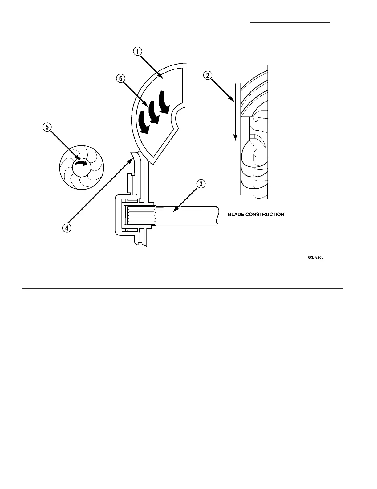
TURBINE
The turbine (1) (Fig. 244) is the output , or driven ,
member of th e converter. The t urbine is moun ted
with in the housing opposit e the impeller, bu t is not
attached t o th e h ousing. The input sh aft is inser ted
through the center of the im peller a nd splined into
the tu rbin e. The design of the t urbine is similar to
the impeller, except the blades of the t urbine ar e
curved in th e opposite direction.
Fig. 244 Turbine
1 - TURBINE VANE 4 - PORTION OF TORQUE CONVERTER COVER
2 - ENGINE ROTATION 5 - ENGINE ROTATION
3 - INPUT SHAFT 6 - OIL FLOW WITHIN TURBINE SECTION
21 - 180 AUTOMATIC TRANSMISSION NAG1 - SERVICE INFORMATION VA