• Tra nsmission fluid tem per ature
• Engine coolant temperatur e
• Input speed
• Th rottle an gle
• Engine speed
OPERATION
The con vert er impeller (driving member) (2) (F ig.
248), which is integra l to the converter housing and
bolted to the engine drive plate, rotates at en gin e
speed. The conver ter tu rbin e (driven mem ber) (1),
which rea cts fr om fluid pressure generat ed by th e
impeller, r otates a nd turns the tra nsmission inpu t
sh aft (4).
TURBINE
As th e fluid that was put in to motion by the impel-
ler blades st rikes th e blades of th e tu rbin e, som e of
the energy an d rotat iona l force is tra nsferr ed int o the
turbine and t he i n pu t shaft . This ca uses both of them
(turbine a nd input shaft) to rotat e in a clockwise
direct ion following th e impeller. As the fluid is leav-
ing the tra iling edges of t he turbine’s blades it con-
tinues in a “hindering” direct ion back towa rd t he
impeller. If th e flu id is not redirected before it strikes
the im peller, it will st rike the im peller in such a
direct ion tha t it would tend to slow it down.
STA TOR
Torque m ultiplica tion is achieved by locking the
st ator’s over-run ning clut ch t o its sh aft. (F ig. 249)
Under sta ll condit ions (t he t urbine is sta tion ary), th e
oil leaving the turbine blades st rikes the face of t he
st ator blades and tr ies to rotate them in a count er-
clockwise dir ection . When this happen s the over-run-
ning clut ch of t he st ator locks a nd h olds the st ator
from rotating. Wit h t he stator locked, the oil strikes
the stat or blades a nd is redirected in to a “helping”
direct ion befor e it enters th e impeller. Th is circula-
tion of oil from im peller to t urbine, tur bine to st ator,
and stator to impeller, can produ ce a ma xim um
torqu e multiplication of about 2.0:1. As th e t urbine
begins to m atch the speed of th e impeller, t he flu id
that was hitting the st ator in such as way as to
cause it to lock-up is no lon ger doing so. In this con-
dition of operation, the stator begins to fr ee wheel
and the converter a cts as a flu id coupling.
Fig. 248 Torque Converter
1 - TURBINE
2 - IMPELLER
3 - STATOR
4 - INPUT SHAFT
5 - STATOR SHAFT
6 - TURBINE DAMPER
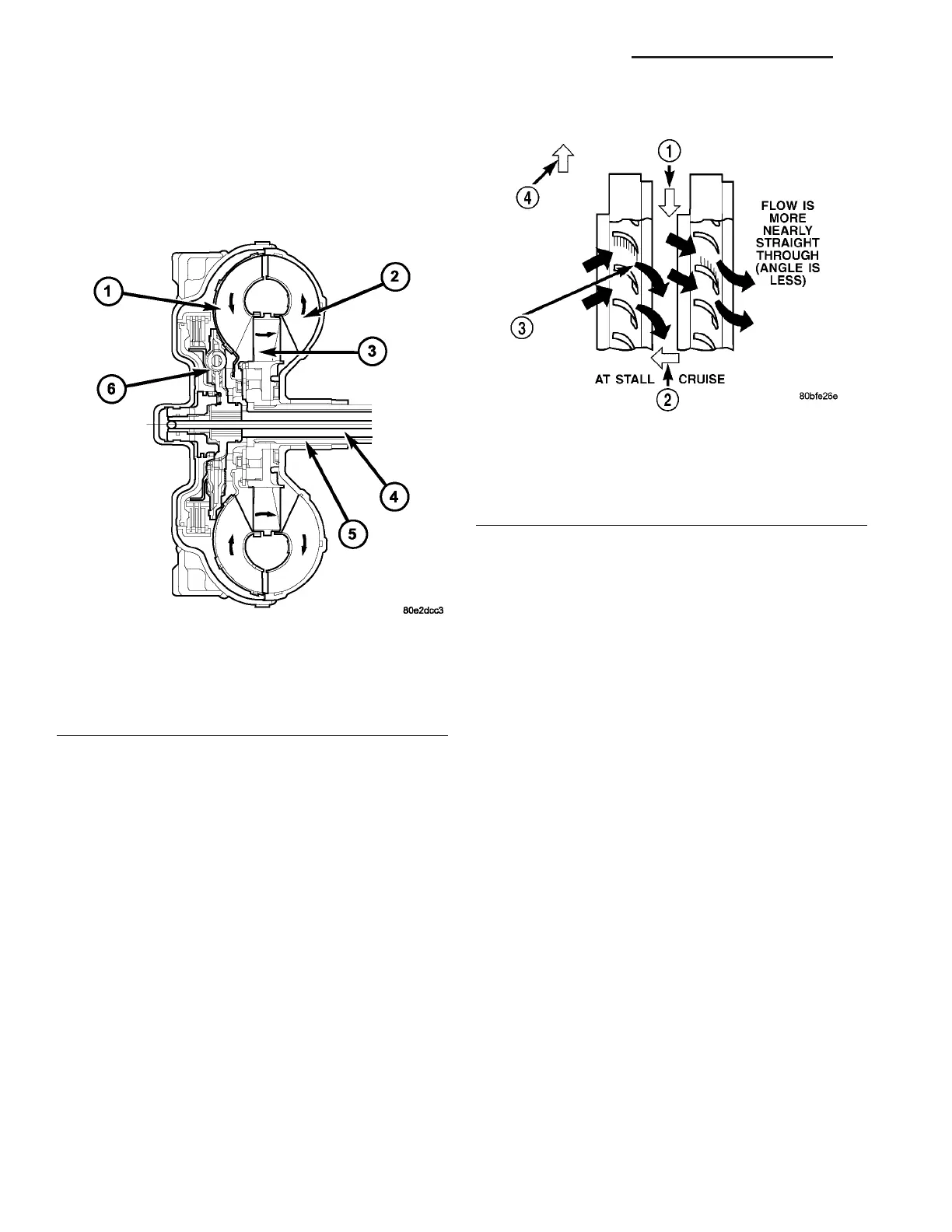
Fig. 249 Stator Operation
1 - DIRECTION STATOR WILL FREE WHEEL DUE TO OIL
PUSHING ON BACKSIDE OF VANES
2 - FRONT OF ENGINE
3 - INCREASED ANGLE AS OIL STRIKES VANES
4 - DIRECTION STATOR IS LOCKED UP DUE TO OIL PUSHING
AGAINST STATOR VANES
21 - 182 AUTOMATIC TRANSMISSION NAG1 - SERVICE INFORMATION VA