TORQUE CONVERTER CLUTCH (TCC)
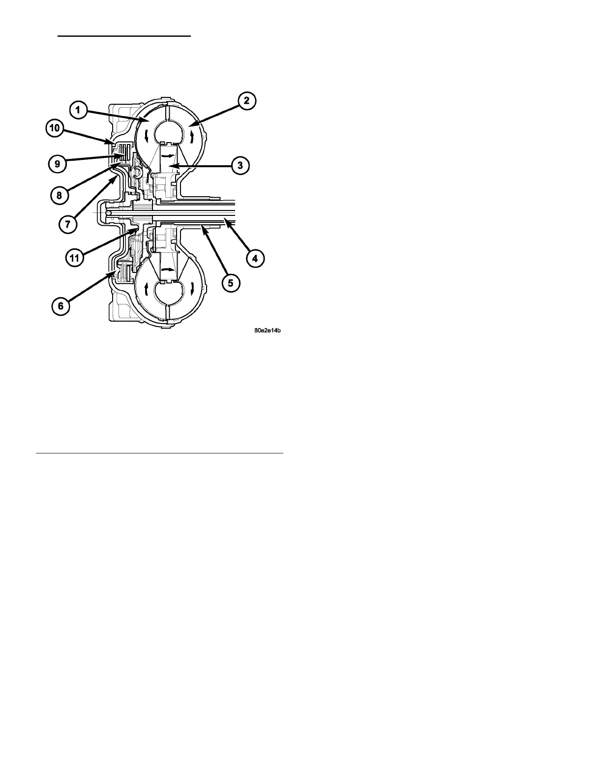
In a sta ndard torqu e converter, the impeller (2)
and tu rbine (1) are r otating at a bout t he same speed
and the stator (3) is freewh eeling, pr oviding no
torqu e multiplicat ion. By applying the tu rbin e’s pis-
ton a nd friction ma terial (9) (F ig. 250), a tota l con-
vert er engagement can be obta ined. Th e resu lt of th is
enga gement is a dir ect 1:1 m echan ical link between
the engine a nd the transmission.
The clu tch can be enga ged in second, th ird, fourth,
and fifth gea r ranges.
The TCM cont rols the torque convert er by wa y of
internal logic softwa re. The pr ogrammin g of the soft-
ware provides t he TCM with control over th e tor que
conver ter solenoid. There are fou r output logic sta tes
that can be applied as follows:
• No EMCC
• Partial EMCC
• Full EMCC
• Gr adual-to-no EMCC
NO EMCC
Under No E MCC conditions, th e TCC Solenoid is
OFF. There are several con ditions th at can resu lt in
NO EMCC opera tion s. No EMCC can be init iated
du e to a fault in the tr ansmission or because th e
TCM does not see the n eed for EMCC under curr ent
dr iving conditions.
PARTIAL EMCC
Partial EMCC operat ion m odu lates the TCC Sole-
noid (dut y cycle) to obtain pa rtial torqu e converter
clutch application. Partia l EMCC operat ion is main-
tained until Full EMCC is called for and actu ated.
During Partia l EMCC some slip does occu r. Part ial
EMCC will usually occur at low speeds, low load a nd
light th rottle sit uations.
FULL EMCC
During Full EMCC oper ation, the TCM increa ses
the TCC Solenoid du ty cycle to full ON after P artial
EMCC con trol brings the engine speed within the
desired slip ra nge of transmission input speed rela-
tive to engine rpm.
GRADUAL - TO - NO EMCC
This oper ation is to soften the chan ge from Full or
Partial E MCC to No EMCC. Th is is done at mid-
throttle by decr easin g the TCC Solenoid dut y cycle.
REMOVAL
(1) Remove tra nsmission and torqu e conver ter
from veh icle.
(2) Pla ce a suit able dra in pa n u nder the converter
housin g end of the t ransm ission.
CAUTION: Verify that transmission is secure on the
lifting device or work surface, the center of gravity
of the transmission will shift when the torque con-
verter is removed creating an unstable condition.
The torque converter is a heavy unit. Use caution
when separating the torque converter from the
transmission.
(3) Pull th e tor que conver ter for ward until t he cen -
ter hu b clears the oil pu mp seal.
(4) Sepa rat e th e torque converter from the tra ns-
mission .
Fig. 250 Torque Converter Lock-up Clutch
1 - TURBINE
2 - IMPELLER
3 - STATOR
4 - INPUT SHAFT
5 - STATOR SHAFT
6 - PISTON
7 - COVER SHELL
8 - INTERNALLY TOOTHED DISC CARRIER
9 - CLUTCH PLATE SET
10 - EXTERNALLY TOOTHED DISC CARRIER
11 - TURBINE DAMPER
VA AUTOMATIC TRANSMISSION NAG1 - SERVICE INFORMATION 21 - 183