(7) In st all mirror. (Refer to 23 - BODY/EXTERI-
OR/SIDE VIEW MIRROR - INSTALLATION)
(8) Adjust door if requir ed. (Refer t o 23 - BODY/
DOOR - F RONT/DOOR - ADJ USTMENTS)
(9) Connect batt ery n egat ive cable.
ADJ U ST M EN T S
ADJUSTMENT
NOTE: Door adjustment measurements should be
taken from stationary or welded body panels like
the roof, rocker or quarter panels.
• During adjustment procedures, it is recom-
mended that all the hinge fasteners be loosened
except for the upper most fasteners. Adjustments
can be made using the upper bolts to hold the door
with final torque of the fasteners occurring after
correct door positioning is achieved.
• A suitable body sealant should be used when
removing or moving the hinges.
(1) Check door alignm ent. (Refer t o 23 - BODY/
BODY STRUCTURE/GAP AND FLUSH - SP ECIFI-
CATI ONS )
(2) If adjustm ent is requir ed, remove latch striker.
(Refer to 23 - BODY/DOOR - FRONT/LATCH
STRIKER - RE MOVAL)
(3) Remove side view mir ror. (Refer to 23 - BODY/
EXTE RIOR/SIDE VIE W MIRROR - REMOVAL)
(4) Loosen h inge bolts and adju st door gap and
align ridge pa ttern as necessar y.
(5) Tighten h inge bolt s t o 25 N·m (18 ft. lbs.).
(6) In st all latch striker and adjust flush measure-
ment as necessar y. (Refer to 23 - BODY/DOOR -
FRONT/LATCH STRIKER - INSTALLATION)
(7) In st all side view mir ror. (Refer t o 23 - BODY/
EXTE RIOR/SIDE VIE W MIRROR - INSTALLA-
TION )
DOOR GLASS
REMOVAL
(1) Remove t he regulator. (Refer to 23 - BODY/
DOOR - FRONT/WINDOW RE GULATOR - POWER
or MANUAL - REMOVAL)
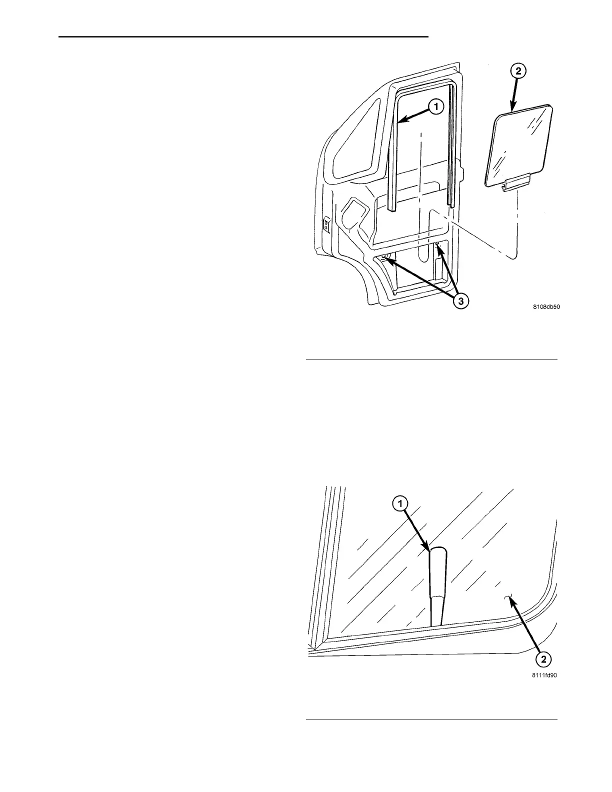
(2) Remove reinforcement bolts. (Fig. 6)
(3) Carefully lower glass in to door and out of run
channel.
(4) Remove glass from door.
INSTALLATION
(1) Carefully place glass into door a nd slide up
into run channel.
(2) Usin g wood wedge, tape or equivalent , secure
gla ss in the up position. (Fig. 7)
(3) In st all reinforcement a nd insta ll the bolts.
Fig. 6 FRONT DOOR GLASS
1 - DOOR RUN CHANNEL
2 - DOOR GLASS
3 - REINFORCEMENT BOLTS
Fig. 7 GLASS SUPPORT
1 - WOOD WEDGE (or equivalent)
2 - WINDOW GLASS
VA DOOR - FRONT 23 - 15