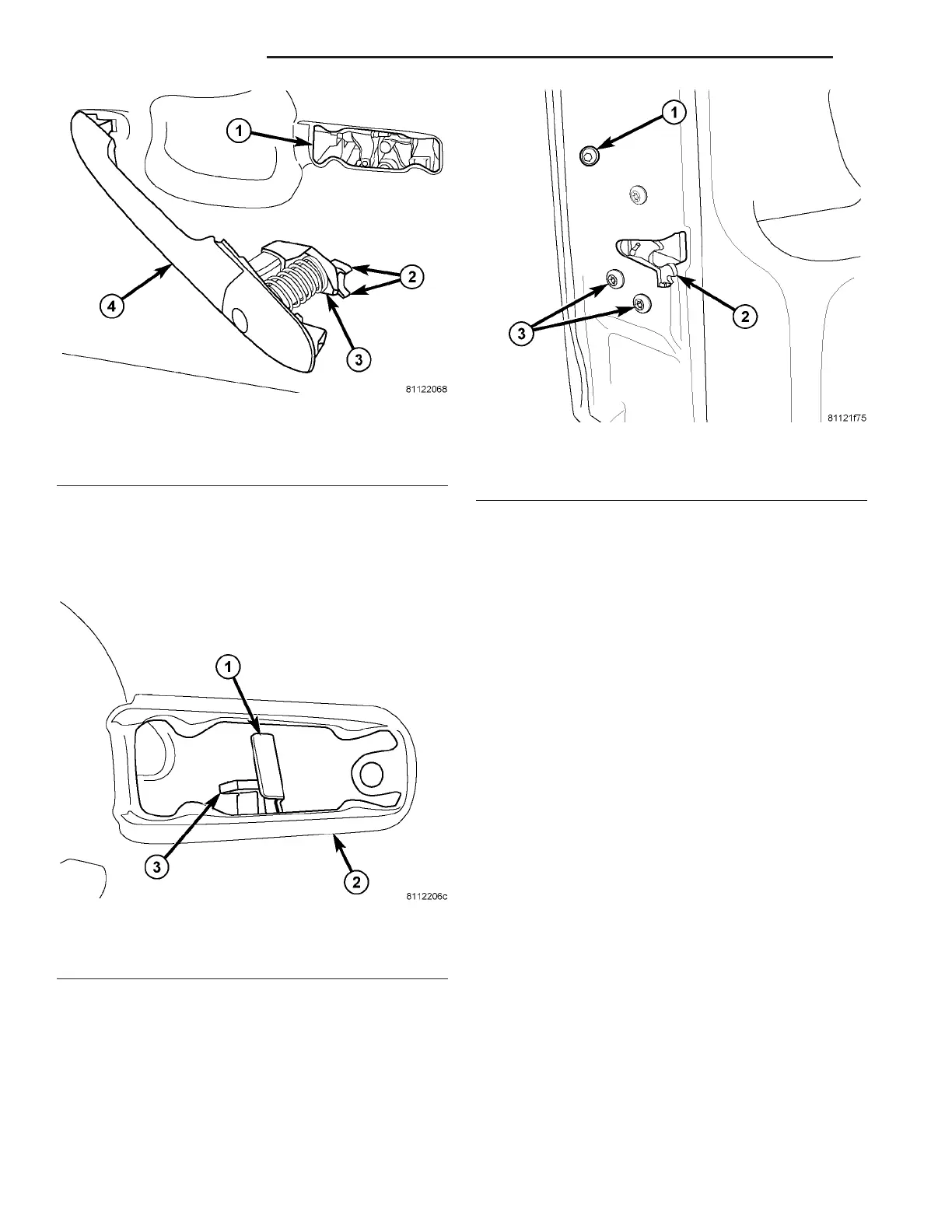
(2) Position rear of ha ndle into la tch opening a nd
enga ge lock a nd latch actuat ion levers wit h the latch
levers. (Fig. 16)
NOTE: Front door shown, rear door similar.
(3) Slide exterior handle towards r ear of door and
insta ll bolt. (Fig. 17)
NOTE: Front door shown, rear door similar.
(4) Tighten bolt to 10 N·m (89 in. lbs.).
HINGE
REMOVAL
NOTE: It is not necessary to remove the door to
replace the hinges if they are replaced one at a
time.
(1) Usin g a grease pencil or equivalent, ma rk th e
position of the h inge on the door.
(2) Remove t he bolts and remove the hin ge. (Fig.
18)
Fig. 15 EXTERIOR HANDLE INSTALLATION
1 - DOOR LATCH OPENING
2 - LOCK ACTUATION LEVER
3 - LATCH ACTUATION LEVER
4 - EXTERIOR HANDLE
Fig. 16 LATCH LEVERS
1 - LATCH LEVER
2 - LATCH OPENING
3 - LOCK LEVER
Fig. 17 EXTERIOR HANDLE
1 - EXTERIOR HANDLE BOLT
2 - LATCH
3 - LATCH BOLTS (3)
23 - 32 D OOR S - R EAR VA