INSTALLATION
(1) In st all hinge and install bolts.
(2) Tighten bolts to 25 N·m (18 ft. lbs.).
(3) Adjust door if necessa ry. (Refer to 23 - BODY/
DOOR - F RONT/DOOR - ADJ USTMENTS)
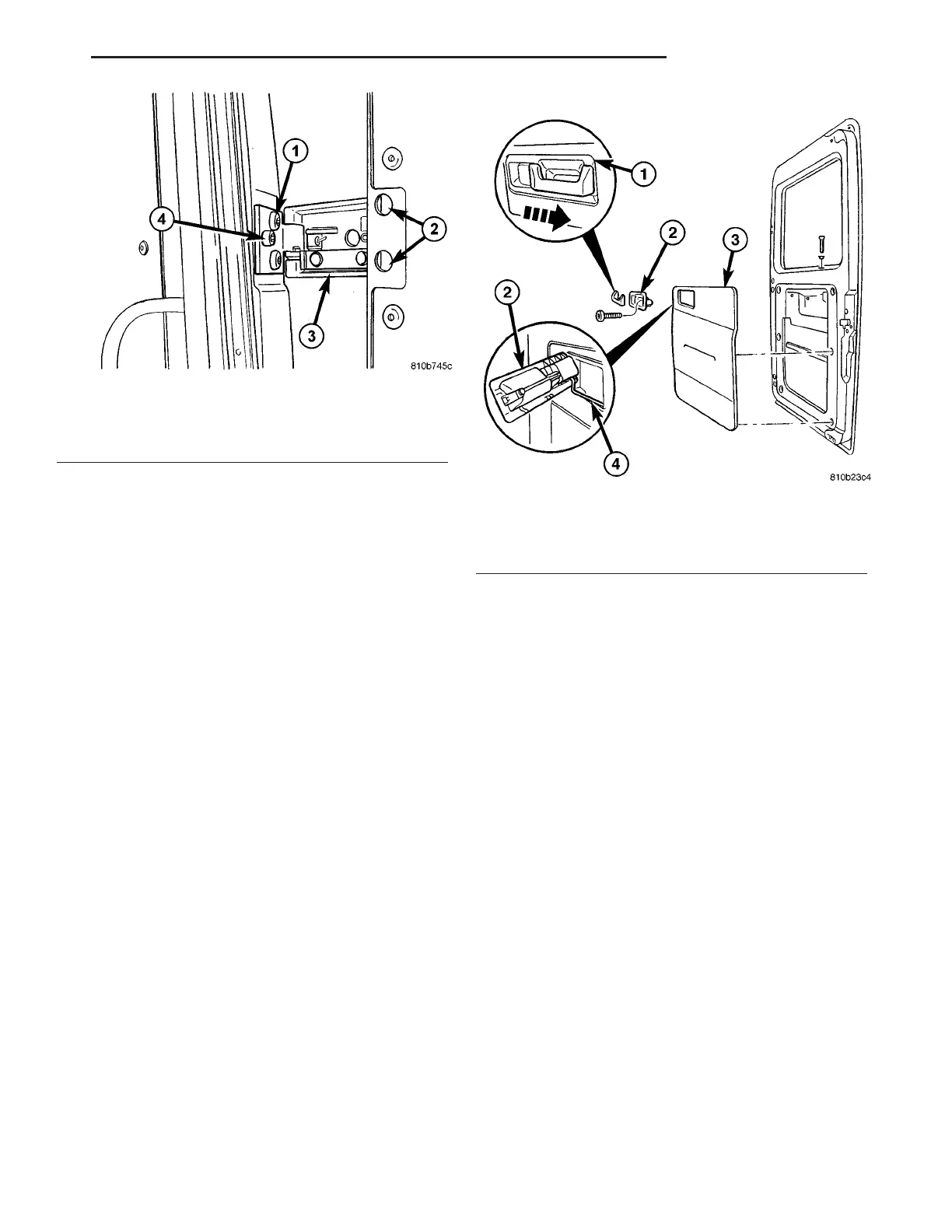
INSIDE HANDLE ACTUATOR
REMOVAL
(1) Remove the handle trim cover. (Fig. 19)
(2) Remove the scr ews and handle.
(3) Disconn ect the latch cable.
INSTALLATION
(1) Connect the latch cable.
(2) In st all han dle and scr ews.
(3) In st all trim cover.
LAT CH
REMOVAL
(1) Disconn ect and isolate battery negative ca ble.
(2) Remove right side trim panel. (Refer to 23 -
BODY/DOORS - REAR/TRIM PANEL - REMOVAL)
(3) Disconn ect lock rod. (F ig. 20)
(4) Remove the scr ews and pull ou t latch from
door.
(5) Disconn ect cable and electr ical connect ors.
Fig. 18 REAR DOOR HINGE
1 - TORX BOLTS BODY SIDE
2 - TORX BOLTS DOOR SIDE
3 - HINGE
4 - ALLEN BOLT
Fig. 19 TRIM PANEL
1 - TRIM
2 - INSIDE HANDLE ACTUATOR
3 - TRIM PANEL
4 - CONTROL CABLE
VA DOORS - REAR 23 - 33