(14) Install the door. (Refer to 23 - BODY/DOORS
- SLIDING/SLIDING DOOR - INSTALLATION)
INSTALLATION
(1) In st all the door by inserting th e center and
upper r oller s int o the tracks a nd sliding the door for-
ward t o the front of each track.
(2) Connect the lower roller a rm an d in st all th e
scr ews.
(3) Tighten t he screws to 25 N·m (18 ft. lbs.).
(4) In st all door st op a nd screws.
(5) Tighten t he screws to 10 N·m (89 in. lbs.).
(6) In st all th e cent er track en d piece and in st all
the scr ew.
(7) Tighten t he screw to 10 N·m (89 in. lbs.).
(8) Check an d adjust door if necessary. (Refer to 23
- BODY/DOORS - SLIDING/SLIDING DOOR -
ADJ USTMENTS)
(9) Connect batt ery n egat ive cable.
ADJ U ST M EN T S
ADJUSTMENT
NOTE: Door adjustment measurements should be
taken from stationary or welded body panels like
the roof, rocker or quarter panels.
A suitable body sealant should be used when
removing or moving the hinges.
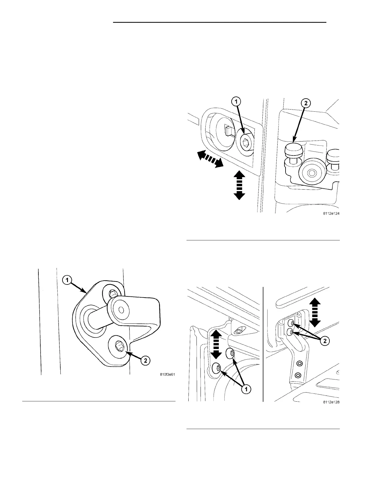
(1) Remove bolt s a nd rem ove str iker. (Fig. 18)
(2) Check gaps and ridge pat tern on door all t he
way around. (Refer to 23 - BODY/BODY STRUC-
TURE /GAP AND FLUSH - SPECIFICATIONS)
NOTE: It must be possible to move the guide wedge
during the entire adjusting procedure. In order to
close the door during adjustment move guide
wedge if necessary.
(3) Loosen guide wedge screws.
Gaps and Ridge Adjustment
(1) Loosen scr ew and adjust rear ridge pattern by
lift ing and lowerin g slidin g door at center roller arm.
(Fig. 19)
(2) Tighten bolt to 45 N·m (33 ft. lbs.).
(3) Loosen upper roller arm scr ews. (Fig. 20)
(4) Loosen lower r oller a rm screws.
(5) Adjust front ridge pat tern by ra ising or lower-
ing door.
(6) Tighten upper and lower roller arm bolts to 25
N·m (18 ft. lbs.).
Fig. 18 LATCH STRIKER
1 - STRIKER
2 - BOLTS
Fig. 19 ADJUST CENTER ROLLER ARM
1 - BOLT
2 - CENTER ROLLER ARM
Fig. 20 UP/DOWN ADJUST
1 - SCREWS (2) UPPER ROLLER ARM
2 - SCREWS (2) LOWER ROLLER ARM
23 - 44 DOORS - SLIDING VA