(3) In st all wedge and insta ll screws.
(4) Close sliding door to adjust closing wedge.
(5) Open door an d tighten scr ews t o 10 N·m (89 in.
lbs.).
TRIM PANEL
REMOVAL
Upper
(1) Remove rivets and remove panel.
Lower
(1) Remove the bolts a nd rem ove the stop bumper.
(Fig. 24)
(2) Remove the inside ha ndle actu ator. (Refer to 23
- BODY/DOORS - SLIDING/INSIDE HANDLE
ACTUATOR - REMOVAL)
(3) Remove the push pin fasteners and rem ove the
trim panel.
INSTALLATION
Upper
(1) In st all trim panel an d repla ce rivets.
Lower
(1) In st all the trim panel an d pu sh pin fastener s.
(2) In st all t he in side handle actuator. (Refer to 23 -
BODY/DOORS - SLIDING/INSIDE HANDLE
ACTUATOR - INSTALLATION)
(3) In st all st op bu mper, bolts and adjust if neces-
sa ry. (Refer to 23 - BODY/DOORS - SLIDING/SLID-
ING DOOR - ADJ USTMENTS)
DOOR GLASS
REMOVAL
(1) Position an assista nt on on e side of the door to
receive t he glass an d weatherstr ip seal.
(2) St art at a n inside, u pper corner. Sepa rate the
seal fr om the window opening. Push th e gla ss and
seal outward from the window open ing. Remove th e
glas s and s e al.
(3) Clean the window open ing.
INSTALLATION
(1) In st all the weat herstrip sea l on t he window
gla ss. Verify t hat th e gla ss is seated in the groove
around the edge of t he seal.
(2) In sert a n installation cord in the wea ther st rip
seal inner groove.
NOTE: Use mineral spirits as a lubricant to aid seal
installation in the window opening.
(3) Position the glass a nd seal in th e window open-
ing.
(4) Pull the installation cord outward and force the
seal lip over the panel flan ge arou nd t he edge of the
openin g.
(5) Seat the sea l inner lip on the panel flange.
Press against the lip a round the edge of the seal.
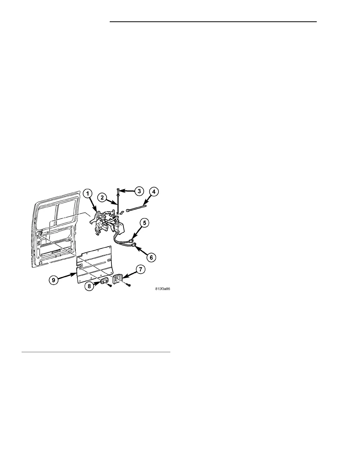
Fig. 24 LOCK ASSEMBLY
1 - LATCH/LOCK CONTROL ASSEMBLY
2 - LOCK ROD
3 - LOCK KNOB
4 - LATCH CONTROL CABLE
5 - ELECTRICAL CONNECTOR
6 - ELECTRICAL CONNECTOR
7 - INTERIOR HANDLE ACTUATOR
8 - STOP BUMPER
9 - TRIM PANEL
23 - 46 DOORS - SLIDING VA