ADJ U ST M EN T S
ADJUSTMENT
SPECI FI CAT I ON S
DESCRIPTION SPECIFICATION
Left and right hood gaps 5 ± 0.5 mm
Flush offset for hood/
fender
≤ 1.0 mm
(1) Check hood to fender gap. Refer to the SPECI-
FICATIONS table.
(2) Loosen hinge to cowl bolts and adjust hood side
to side, if necessa ry.
(3) Tighten bolts to 23 N·m (17 ft. lbs.).
(4) Check h ood to fender flushness. Refer to the
SPECIFICATIONS ta ble.
(5) Loosen h inge to hood nu ts a nd adjust hood u p
and down, if necessary.
(6) Tighten n uts to 23 N·m (17 ft. lbs.).
(7) Loosen safety la tch bolt s. (F ig. 2)
(8) Adjust lat ch to align with hood latch, if neces-
sary.
(9) Tighten safet y la tch bolt s.
(10) Loosen safety la tch str iker pin lock nut a nd
adju st striker pin up an d down to adjust front of
hood to fender flushn ess. Refer to the SP ECIFICA-
TION S t a ble.
(11) Tighten lock n ut fully.
(12) Adjust hood slam bumper s up or down if nec-
ess a r y.
LAT CH
REMOVAL
(1) Remove bolt s a nd rem ove latch . (Fig. 3)
(2) Disconn ect lat ch cable.
INSTALLATION
(1) Connect latch cable a nd install lat ch.
(2) In st all the bolts a nd tighten .
LAT CH RELEASE CABLE
REMOVAL
(1) Remove t he r elea se han dle scr ews and r elease
handle.
(2) Disconn ect the ca ble fr om the h andle.
(3) Remove the latch. (Refer to 23 - BODY/HOOD/
LATCH - RE MOVAL)
(4) Route cable thr ough cowl pa nel and remove
from engine compar tment.
INSTALLATION
(1) Route cable thr ough engine compar tmen t and
into pa ssenger com pa rtment as necessa ry.
(2) In st all latch. (Refer to 23 - BODY/HOOD/
LATCH - INSTALLATION)
(3) Connect cable to release handle.
(4) In st all release h andle and insta ll t he screws.
LAT CH RELEASE H AN DLE
REMOVAL
(1) Remove the screws and r emove the release
handle.
(2) Disconn ect the ca ble fr om handle.
INSTALLATION
(1) Connect latch cable t o release h andle.
(2) In st all han dle and install the scr ews.
Fig. 2 SAFETY LATCH
1 - SAFETY LATCH
2 - BOLTS
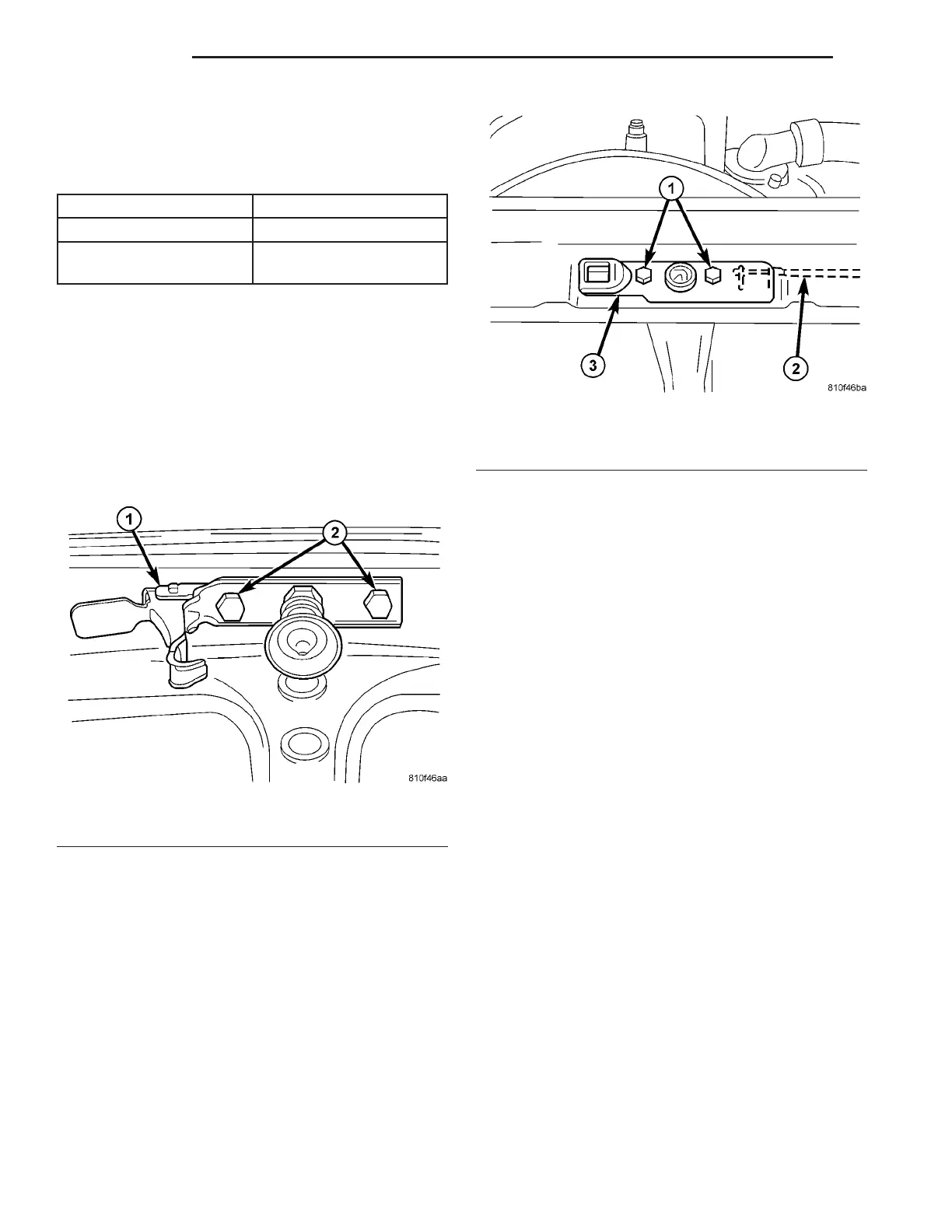
Fig. 3 HOOD LATCH
1 - BOLTS
2 - LATCH CABLE
3 - LATCH
23 - 52 H OOD VA