(6) Char ge the refrigera nt system (Refer t o 24 -
HEATING & AIR CONDITIONING/PLUMBING -
STANDARD PROCE DURE ).
AI R OU T LET T EM PERAT U RE
SEN SOR
DESCRIPTION
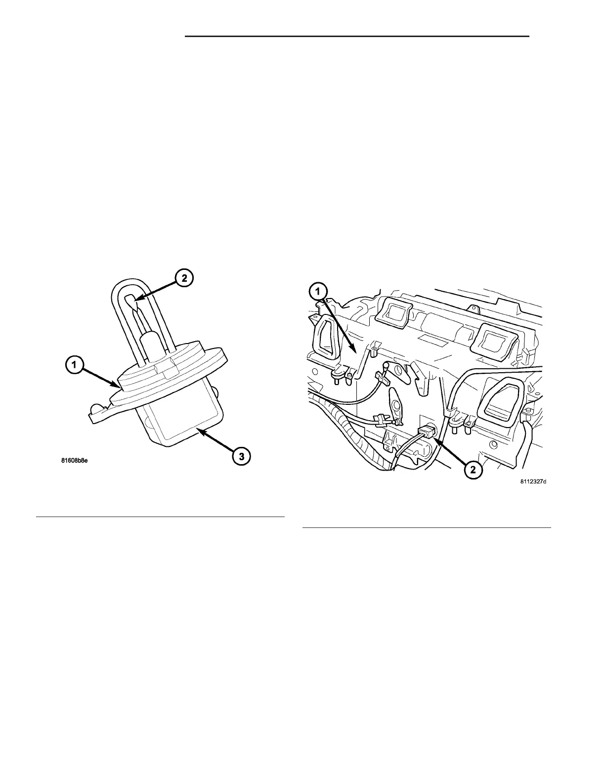
The a ir out let t empera ture sensor is a two-wire
temper ature sensing element tha t det ects the t em-
perat ure of the air com ing out of t he hea ter hou sing
unit (Fig. 11). The sensor is attached to heater hou s-
ing un it directly beh ind th e ATC hea ter-A/C control
pa nel. Th e t hermistor will chan ge resistance as t he
temper ature cha nges.
OPERATION
The air outlet temper ature sensor monitors t he
temper ature of th e air comin g out of th e heater h ous-
ing un it. The sensor will change its in tern al resis-
tance in respon se to the tempera tures it m onitors.
The ATC con trol module is connect ed to the sen sor
through a sen sor ground circu it and a sensor signa l
circuit. As the air t empera ture increases, the resis-
tance of t he sensor decreases an d the volta ge moni-
tored by th e m odu le decreases. Th e opera tin g ran ge
of th e air ou tlet t empera ture sen sor is 0° C (32° F)
and 95° C (203° F). The modu le uses t his mon itor ed
volt age rea ding to an indication of the out let air tem -
perat ure. Th e ATC contr ol module makes adjust-
ment s t o m aintain the requested in terior
temper ature by cycling both t he A/C compressor an d
solenoid heater valve on a nd off.
The a ir outlet tem per atu re sensor is diagn osed by
performing th e ATC Function Test using th e DRBIII!
sca n tool. Refer to Body Dia gnostic Procedu res.
The air outlet tempera tur e sen sor can not be
adju st ed or repa ired, and if fa ulty or damaged, it
must be r eplaced.
REMOVAL
(1) Disconn ect and isolate the battery nega tive
cable.
(2) Remove th e heater-A/C control from the instru-
ment pa nel (Refer to 24 - HEATING & AIR CONDI-
TIONING/CONTROLS/A/C HEATER CONTROL -
REMOVAL).
(3) Disconn ect the wire ha rness connector from th e
air outlet tem perature sen sor (Fig. 12).
(4) Remove the a ir outlet t empera ture sen sor from
the h eater housing.
INSTALLATION
(1) In st all the air out let t empera ture sensor ont o
the h eater housing.
(2) Connect t he wire ha rness connector to t he air
outlet temper ature sensor.
(3) In st all t he heater-A/C contr ol int o the instru-
ment pa nel (Refer to 24 - HEATING & AIR CONDI-
TIONING/CONTROLS/A/C HEATER CONTROL -
INSTALLATION).
(4) Reconnect t he battery negative cable.
Fig. 11 Air Outlet Temperature Sensor
1 - AIR OUTLET TEMPERATURE SENSOR
2 - NTC THERMISTOR
3 - WIRE CONNECTOR
Fig. 12 Air Outlet Temperature Sensor
1 - HEATER HOUSING
2 - AIR OUTLET TEMPERATURE SENSOR
24 - 16 CONTROLS-FRONT VA