AM BI EN T T EM PERAT U RE SEN -
SOR
DESCRIPTION
The ambient a ir t empera ture sensor is a variable
resistor that monitors the air tempera ture out side of
the vehicle. Th e ambient air temperatur e sen sor is
connect ed to the instrument cluster through a t wo-
wire harness lea d an d connector of the vehicle elec-
trical syst em (Fig. 13). The instrument cluster sen ds
out a messa ge on th e CAN bus to the ATC control
module wh ich uses the sen sor data to mainta in opt i-
mum cabin temper ature levels.
The ambient air temper ature sensor is mou nted to
the front licence pla te bra cket by three integral
retaining tabs.
OPERATION
The a mbient temper ature sensor is a variable
resistor that opera tes on a five-volt refer ence signal
sent t o it by the in st rument cluster. Th e resistan ce in
the sen sor cha nges as temperatur e changes. Based
upon the resistan ce in the sen sor, the instr umen t
cluster sends the ATC contr ol module a specific volt-
age on th e tempera ture sensor signal circu it, which
is pr ogra mmed to correspond to a specific temper a-
ture.
The am bient t empera ture sen sor is diagnosed
using the DRBIII! sca n tool. Refer to Body Dia gnos-
tic P rocedur es.
The a mbient temperature sen sor can not be
adju st ed or repa ired and, if faulty or dam aged, it
must be r eplaced.
REMOVAL
(1) Disconn ect and isolate the battery nega tive
cable.
(2) Remove the front license pla te bra cket (Refer
to 23 - BODY/EXTE RIOR/LICENSE PLATE
BRACKET - REMOVAL).
(3) Disconn ect the wire ha rness connector from th e
ambient tempera ture sensor (Fig. 14).
(4) Disengage the sen sor r etaining ta bs a nd
remove the ambient t empera ture sensor from the
front license plate bracket.
INSTALLATION
(1) In st all the am bien t tem perat ure sensor onto
the front license plate bracket. Make sure th e retain-
ing tabs a re fully engaged.
(2) Connect th e wire harness con nector to the
ambient tempera ture sensor.
(3) In st all the front licen se plate bracket (Refer to
23 - BODY/EXTE RIOR/LICENSE PLATE BRACKET
- INSTALLATION).
(4) Reconnect t he battery negative cable.
BLOWER M OT OR RESI ST OR
DESCRIPTION
This tem perat ure control system uses a blower
motor resist or (Fig. 15). The blower motor resistor is
mounted to the top of ventilation housin g located in
the engine compartment. The blower mot or resist or
consists of a molded plastic mounting plate with a n
integra l reta ining tab and wire connector recepta cle.
Concealed behind th e m ounting plate are coiled resis-
tor wir es conta ined within a ceram ic hea t sink.
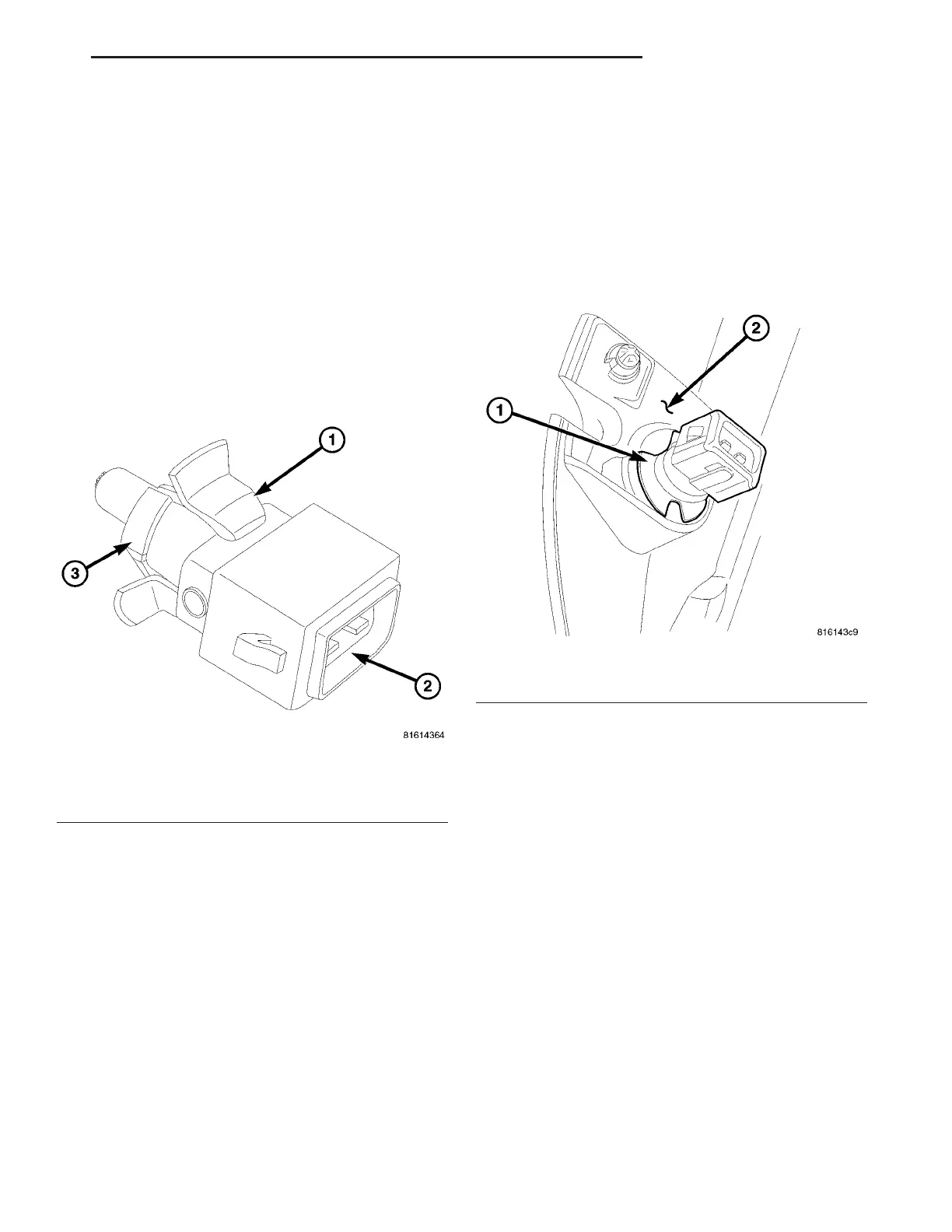
Fig. 13 Ambient Air Temperature Sensor
1 - AMBIENT TEMPERATURE SENSOR
2 - WIRE HARNESS CONNECTOR
3 - RETAINING TABS (3)
Fig. 14 Ambient Temperature Sensor
1 - AMBIENT TEMPERATURE SENSOR
2 - FRONT LICENSE PLATE BRACKET
VA CONTROLS-FRONT 24 - 17